As I was going though some of my old pictures I could see the history of my invention. First I built what was called a 'thumper' on the Internet. To make a 'thumper' essentially you take the flash from a camera and add a coil in series with the flash tube. This 'thumper' design is available on the Internet just google for a 'magnetic thumper' or 'magnetic thumpy'. Below is a picture of my version of that device.
 Next I replaced the flash tube with a big SCR. I had a pile of those big SCR's that were left over from making a time machine, but they were accidentally sold at the Rochester Ham Fest in around 2005. You can see them in the background of the picture. I also started adding more capacitors. Notice the home made aluminum washer sitting on the coil. That was from before I discovered that hard drive platters make great aluminum washers. As you can tell I was already sending aluminum washers into flight. In those early days the washer flew just a few inches.
 Soon I took the washer launcher to the next level. First I used 4 big capacitors and then later I stepped up to 8 of those big capacitors. I fried the old SCR and then replaced it with an ED431825 that can handle 1.8 KV (1800 Volts) and 250 amps continuous and 6.5 KA peak (6500 Amps). This design started out with one MOT (Microwave Oven Transformer) then for a while it had two MOT's.
At some point I added the flat Coil shown below. It was wound a few turns at a time then those turns were glued down and the next few turns were added. A rotating stick held the wire down while the glue was drying. The glue was of a flexible kind. At some point the wood was shattered into pieces, so it was replaced with Plexiglas. That was a bad idea. The Plexiglas shattered on the first test launch.

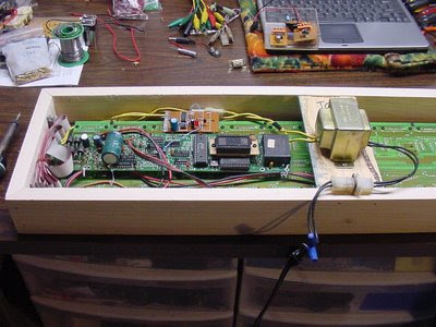
I am upgrading the 8 capacitor 800 volt model to now operate with up to 1600 volts. All of the capacitors had to be turned 90 degrees so that they can be connected in series instead of parallel. Here is the preliminary schematic, it is missing the 10 amp fuse, and that is a 1 meg resistor to the voltmeter that is located on the front panel.

There were two problems with the first test run of the new design. The 10 amp fuse blew because it now draws more current than that. I replaced it with a 15 amp fuse. The next problem is that the meter pegs. I was using a digital volt meter as well and it was not supposed to exceed 600 volts but it survived at 1200 volts. As far as the can crushing goes it did not crush it much more than the 800 volt model had crushed it.

Before testing it a second time I changed the resistor to the meter to 2.5 meg. The meter now reads 2.5 KV full scale. I also shortened the wire to the coil to 1/2 of the original length. The next test was at 1.6 KV and it resulted in the flattest soda can yet. The video is being
uploaded to YouTube.