My Arduino Based 25 million samples per second DSO Oscilloscope project is underway. Years ago I made several printer port projects that were in my book "Digital and Computer Projects". Over the years some of them were updated to work with a serial port using either a 68HC11 or a Basic Stamp. Now I am starting work on redoing them using an Arduino. My first projects were earthquake prediction and LED signs. Next comes a 25 MSPS DSO Oscilloscope. Currently I am reusing the old PCB from the Printer Port Scope project.
I went looking for my old pictures and schematic on the Internet and somewhere around when Geo Cities closed down all of my old schematics were lost. I am now searching my old hard drives to try to find them.
This is the block diagram of the prototype. As you can see it was very complicated. I built it using wirewrap about 15 years ago.
This is the block diagram of the simplified version that was used for the printer port O'scope.
Here is the analog input section. I am in the process of adding a LF351 input buffer IC.
This is the schematic of the memory section. It has the A to D converter and a FIFO.
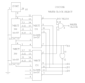
This is the schematic of the clock, I left out a third 74390 that really should still be there.
Here is the PCB from the last version of the Printer Port Scope that I am reusing with the Arduino.
Tuesday, January 10, 2012
Tuesday, January 3, 2012
Targus Universal Charger Repair
Recently I fixed a Targus Universal Charger. This is the second time I have worked on one of these. If only I could remember what the problem was the last time, I could save myself lots of work. The symptoms are that there is no power at the output jack, and changing the jack does not fix the problem.
First I checked the power cable and it had power on the yellow main conductor to the shield. So it had to be the jack right? As you can see in the picture I tore the jack all to pieces to no avail. The actual problem is that the interchangeable jacks are ALL bad! They have to be broken apart and then re-solder the center connector to the circuit board. You might want to re-solder the grounds too while you are in there.
I swapped the rebuilt jack to the AC adapter end in the picture.
The connection color code from the end with a metal plate is:
Red
White
Yellow-Power
Ground-Sield
Blue


