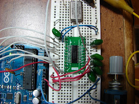
The first picture is of a rebuilt version of the CA3306 circuit.
Next I tried a TLC5510. The results were a bit noisy as seen in the next picture.
A picture of the TLC5510 screen. The noise might not be the fault of the A to D converter. The noise was cured by synchronizing the clocks.
TDA8703 Analog to Digital converter being tested. At first it did not work until I increased the power from 4.2 volts (from USB) to 5 volts via an AC adapter.
I found a way to synchronize the clocks and thus reduce the amount of glitches! Here is the video.
Here is a Youtube video showing the TLC5510 running without the clock glitches.
Here is a video showing a completed Arduino Oscilloscope with working selection switches.


code please
ReplyDeleteHi, I'd love to build this but I have no coding experience (or little) do you give out your code?
ReplyDeleteThanks
Gary
So, are the codes available for this project sir?
ReplyDeleteI would like to build this please Ben
My code is elsewhere on my blog and in my book "Arduino Oscilloscope Projects" available on Amazon.com
ReplyDeleteHi Bob,
ReplyDeleteThis is Arun from India.
I purchased your book yesterday. Very Interesting read.
I'm software engineer trying to learn hardware stuff. I have the following questions for you.
1. Can i use TLC5510/TDA8703 to read SPI data. SPI interface data transfer rate is at least 10mbps. My requirement is to check if data is transferred or not in the interface.
2. The TDA8703 can read up to 40MHZ. Is it possible that can read SPI interface data.
3. Arduino UNO operates at 8MHZ/16Mhz. So if i use TDA8703/TLC5510 should i go ahead and use FIFO IC ?
Arunachalam - You will need a FIFO. There is also a cheap little USB 8 channel logic analyzer that could do the job. It is less than $20 on eBay. It works up to 25MHz.
ReplyDeleteMY code is at: http://bobdavis321.blogspot.com/2015/07/22-or-24-or-28-inch-spi-tft-lcd-ili9341.html
ReplyDeleteHello Bob,
ReplyDeleteIm using ADC CA3306 for my raspberry pi oscilloscope project.
1. What is the value of frequency clock you supply for your CA3306?
2. and what is the most suitable clock generator to supply for the CA3306? is it any IC clock generator can be used? or I take from my Pi?
Any 5-10 MHz clock will work. For the Arduino I use 8 MHz and synchronize the clocks.
ReplyDelete