I also tried painting the parts for the first time. I used paint-able caulk first, then several layers of a sand-able undercoat followed by at least 2 layers of paint. This next picture shows the results.


I modified the gear for the mouth and the ears as well. I wanted ears that were fairly flat, but that resulted in the magnet hitting the jaw mechanism. I will have to find some lower profile speakers.
I also located and added a base. The real inMoov robot has more than just a head, but I wanted to stop there for now. I had to cut the throat piston off at about one inch shorter to fit properly with the stand.

Here is what the completed robot head looked like.

I also recorded a video of me testing the servos to see if everything worked. I used some MG958 servos that are twice as powerful as standard servos but I was not sure if they would be powerful enough.
Nice.
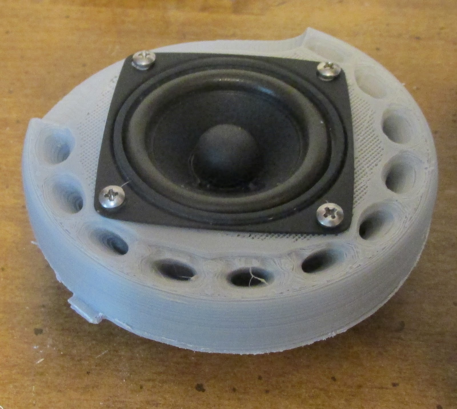
ReplyDeleteLooks like you are getting some under-extrusion (the holes) and even over-extrusion (the over fills). You may want to check your extruder and see if you are getting any slipping (you may hear clicking) or see filament tearing) if there is a lot of retraction used. I have had this over the years myself caused by too high of a retraction setting, printing too fast, not having the hot-end hot enough, worn out hot end flow track, under powered extruder stepper or bad hob-gear. If you are using Teflon tube to feed the filament in with, it could jam in there as well.
I read your whole content it’s really interesting and attracting for new reader.
ReplyDeleteThanks for sharing the information with us.
1.8inch lcd display screen in Germany
1.77inch tft display screen in USA
1.3inch lcd display screen in Poland
2.4inch lcd display in Poland
2.8inch tft module in Germany
4.3inch lcd display screen in France
2.4 inch TFT Display
Hey Bob, I stumbled across one of your books about Addressable LED lights. There, you are giving great instructions on how to connect 8 strips of addressable LEDs to your arduino board. My soldering skills are non-existing :), is there any other way with connectors to complete this setup without any soldering, please? I'm struggling with the part about connecting to the power supply ( i bought a 5V 15amps)? Im not following your projects here and this one is really interesting, after i finish up the LED, i will attempt something similar.
ReplyDeleteThanks in advance.
Pete
Scott,
ReplyDeleteIt was under extrusion. There was a lump between the teflon tube and the heat break. It eventually became so bad that I had to disasemble the printhead to see what was happening. The lump had grown to nearly 1/2 an inch in size and was apparently pushing the teflon tube back out of the printhead.
Pete,
ReplyDeleteI do not know how to connect the power supply to the LED strips without soldering. You can order 8 LED strips but you will need to connect all of their positives and negatives together and to the power supply. Then the 8 signals need to be connected to the arduino. Maybe you could use crimp connectors and binding posts?