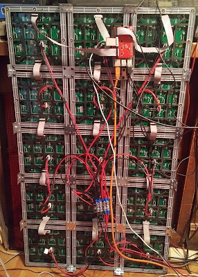
I have written two programs to test LED panels after someone sold me a pile of them with many bad LED's. Some panels had over 30 LED's that were not working. He also shipped them with no padding between the LED's! This resulted in smashed LED's and some of the alignment nubs were broken off. Fortunatly with some soldering I was able to reduce the number of bad LED's to 3 or 4 per panel. Now I can use them for testing out programs and configurations. Some LED's had broken runs but most of them just needed to be resoldered.
The first program tests the colors and leaves the panel white for quickly testing if the LED's just soldered are working. This does not work on 16S panels for some reason.
// RGBcolors test for Adafruit RGBmatrixPanel library.
// For testeing LED arrays for bad bits.
#include <RGBmatrixPanel.h>
#define CLK 8 // USE THIS ON ARDUINO UNO, ADAFRUIT METRO M0, etc.
#define OE 9
#define LAT 10
#define A A0
#define B A1
#define C A2
#define D A3
// Does not work with 16S panels if you add "D" nothing happens!
RGBmatrixPanel matrix(A, B, C, CLK, LAT, OE, false);
void setup() {
matrix.begin();
// fill the screen with colors
matrix.fillRect(0, 0, 32, 32, matrix.Color333(0, 7, 0));
delay(1000);
matrix.fillRect(0, 0, 32, 32, matrix.Color333(7, 0, 0));
delay(1000);
matrix.fillRect(0, 0, 32, 32, matrix.Color333(0, 0, 7));
delay(1000);
matrix.fillRect(0, 0, 32, 32, matrix.Color333(7, 7, 7));
delay(1000);
}
void loop() {
}
The next program is for sorting LED panels by how they are internally wired. There are 16S, 8S (There are many varieties of 8S) and 4S panels. It scans all LED's one at a time.
I could not get this to work with the normal drivers so I wrote my own using "bit banging". Its slow but works great! Note:This program was improved in March of 2021, it runs much better now! // RGB bitbang test bits by scanning
#define CLK 8
#define OE 9
#define LAT 10
#define A A0
#define B A1
#define C A2
#define D A3
#define R1 2
#define G1 3
#define BL1 4
#define R2 5
#define G2 6
#define B2 7
int tbit;
int row;
int col;
void setup() {
pinMode(A, OUTPUT);
pinMode(B, OUTPUT);
pinMode(C, OUTPUT);
pinMode(D, OUTPUT);
pinMode(CLK, OUTPUT);
pinMode(OE, OUTPUT);
pinMode(LAT, OUTPUT);
pinMode(R1, OUTPUT);
pinMode(G1, OUTPUT);
pinMode(BL1, OUTPUT);
pinMode(R2, OUTPUT);
pinMode(G2, OUTPUT);
pinMode(B2, OUTPUT);
}
void loop() {
// Set sequential bits
for (row=0; row<16; row++){
for (col=0; col<64; col++){
for (tbit=0; tbit<64; tbit++){
digitalWrite(R1, LOW);
digitalWrite(G1, LOW);
digitalWrite(BL1, LOW);
if (tbit <= col){
digitalWrite(R1, HIGH);
// digitalWrite(G1, HIGH);
// digitalWrite(BL1, HIGH);
}
digitalWrite(CLK, HIGH);
digitalWrite(CLK, LOW); //Clock data in
}
// latch and display results
digitalWrite(OE, HIGH); // disable output while latching data.
digitalWrite(LAT, HIGH);
// select next column if it has changed
digitalWrite(A, LOW);
digitalWrite(B, LOW);
digitalWrite(C, LOW);
digitalWrite(D, LOW);
// update row selection
if ((row & 0x0001)>0)digitalWrite(A, HIGH);
if ((row & 0x0002)>0)digitalWrite(B, HIGH);
if ((row & 0x0004)>0)digitalWrite(C, HIGH);
if ((row & 0x0008)>0)digitalWrite(D, HIGH);
// delay(5); // dim display
digitalWrite(LAT, LOW);
digitalWrite(OE, LOW);
delay(50);
}
}
}