Tuesday, May 28, 2013

Silent Radio LED sign, removing the three Green LED arrays

I decided to saw off the three Green LED arrays.  To my surprise, I lost three columns of the red Arrays as well as clock and data.  To get the clock and data going again I had to tap into the first 4015 clock and data in.  To fix the three missing columns I had to tap into the first three outputs of the first 4015 and route them through inverters and resistors to the first three columns.  You can see those mods in the picture below.

Then I also added 82 ohm resistors across the 100 ohm resistors to get a little more brightness.  They can be seen in this picture.

Wednesday, May 15, 2013

16 by 40 Dual Color LED Sign being sold on eBay Part 2

I have finally made the sign work! It takes a slight trick in the code to send the serial bit to the 4015's for the rows.  It is " if (row= =0) digitalWrite(OutEnable, LOW);" in the code.

Here is what it looked like when it first came to life.  I was sending the code for making a smiley face.


This is what it looks like with an Arduino running the code that is listed below.

This is what it looks like connected to an Arduino Pins 1-6, and a 5 volt 2.5 amp AC adapter.  For the schematic and pin connections see my older post on this sign.


Here is the code to make it work;
//********************************************//
//  Name    : LED 24x40 array Driver    
//  Author  : Bob Davis                           
//  Date    : 12 May, 2013                   
//  Version : 1.0                                
//********************************************//
// Pins for the clocks and data
int TCLK = 1;
int TSerial = 5;
int BCLK = 6;
int BSerial = 3;
int Strobe = 4;
int OutEnable = 2;

// arrays to say Arduino
byte Tbitmap[][8] = {  //red characters
  {0,  4, 10, 17, 17, 31, 17, 17}, //A
  {0, 0,0,0,0,0,0,0},
  {0, 28, 18, 17, 17, 17, 18, 28}, //D
  {0, 0,0,0,0,0,0,0},
  {0, 14, 04, 04, 04, 04, 04, 14}, //I
  {0, 17, 25, 25, 21, 19, 19, 17}, //N
  {0, 14, 17, 17, 17, 17, 17, 14}, //O
};
byte Bbitmap[][8] = {  //green characters
  {0,  4, 10, 17, 17, 31, 17, 17}, //A
  {0, 30, 17, 17, 30, 20, 18, 17}, //R
  {0, 0,0,0,0,0,0,0},
  {0, 17, 17, 17, 17, 17, 17, 14}, //U
  {0, 14, 04, 04, 04, 04, 04, 14}, //I
  {0, 0,0,0,0,0,0,0},
  {0, 14, 17, 17, 17, 17, 17, 14}, //O
};
// Set the pins to output to the array
void setup() {
  pinMode(TCLK, OUTPUT);
  pinMode(TSerial, OUTPUT);
  pinMode(BCLK, OUTPUT);
  pinMode(BSerial, OUTPUT);
  pinMode(Strobe, OUTPUT);
  pinMode(OutEnable, OUTPUT);
}
void loop() {
  for (int row = 0; row < 8; row++){   //there are actually 16 rows
    for (int character = 7; character >=0; character--){
      for (int shiftbit = 0; shiftbit < 6; shiftbit++){
      digitalWrite(TSerial, HIGH); 
      digitalWrite(BSerial, HIGH);
      if bitRead(Tbitmap[character][row],shiftbit) digitalWrite(TSerial, LOW); 
      if bitRead(Bbitmap[character][row],shiftbit) digitalWrite(BSerial, LOW); 
      digitalWrite(TCLK, HIGH); 
      digitalWrite(TCLK, LOW);
      digitalWrite(BCLK, HIGH); 
      digitalWrite(BCLK, LOW);
      }   }
    digitalWrite(OutEnable, HIGH);  // turns off display
    if (row==0) digitalWrite(OutEnable, LOW);  // turns on display
    //latch the data
    digitalWrite(Strobe, LOW);  
    digitalWrite(Strobe, HIGH);
    digitalWrite(OutEnable, LOW);  // turns on display
    delay(.5);   
}  }  

Thursday, May 9, 2013

Dual Color Scrolling LED sign using Cadaces modules and Arduino.

A lot of people have requested that I write a dual color scrolling program for the Cadaces modules.  Well I have done that!  I have also reversed the scrolling by turning the sign over.  Turn the sign over so that the Arduino now connects on the left side.  This also uses the new quick and easy connection pinout.

Here is a link to the video on YouTube:
http://youtu.be/znCA6V8arLw

Here is the code (If blogger will let me upload it).

//**************************************************************//
//  Name    : Cadaces dual color Scrolling                      //
//  Author  : Bob Davis                                         //
//  Date    : 2 May, 2013                                      //
//  Version : 1.0                                               //
//  Based on work of Hari Wiguna - http://g33k.blogspot.com/    //
//****************************************************************
// Pins for the row and data drivers
int row1Pin = 2;
int row2Pin = 7;
int row3Pin = 1;
int rowEnable = 8;
int rclockPin = 6;
int clockPin = 3;
int dataPin = 5;
int gdataPin = 4;   

// Set the pins to output to the circuit
void setup() {
  pinMode(clockPin, OUTPUT);
  pinMode(dataPin, OUTPUT);
  pinMode(row1Pin, OUTPUT);
  pinMode(row2Pin, OUTPUT);
  pinMode(row3Pin, OUTPUT);
  pinMode(rowEnable, OUTPUT);
  pinMode(rclockPin, OUTPUT);
  pinMode(gdataPin, OUTPUT);
}

//=== B I T M A P ===
// Bits in this array represents one LED of the matrix
// 8 is number of rows, 10 is number of LED matrixes we have
byte bitmap[8][10]; // Change the 10 to however many matrices you want to use.
byte gbitmap[8][10]; // Change the 10 to however many matrices you want to use.
int numZones = sizeof(bitmap) / 8; 
//int numZones = sizeof(gbitmap) / 8; 
// I will refer to each group of 8 columns (represented by one matrix) as a Zone.
int maxZoneIndex = numZones-1;
int numCols = numZones * 8;

//=== F O N T ===
// Font courtesy of aspro648
// http://www.arduino.cc/cgi-bin/yabb2/YaBB.pl?num=1203747843/22
// First char is @, next is A, B, etc.  Only upper case, no symbols.  
// The @ will display as space character.
byte alphabets[][5] = {
  {0,0,0,0,0},
  {31, 36, 68, 36, 31},
  {127, 73, 73, 73, 54},
  {62, 65, 65, 65, 34},
  {127, 65, 65, 34, 28},
  {127, 73, 73, 65, 65},
  {127, 72, 72, 72, 64},
  {62, 65, 65, 69, 38},
  {127, 8, 8, 8, 127},
  {0, 65, 127, 65, 0},
  {2, 1, 1, 1, 126},
  {127, 8, 20, 34, 65},
  {127, 1, 1, 1, 1},
  {127, 32, 16, 32, 127},
  {127, 32, 16, 8, 127},
  {62, 65, 65, 65, 62},
  {127, 72, 72, 72, 48},
  {62, 65, 69, 66, 61},
  {127, 72, 76, 74, 49},
  {50, 73, 73, 73, 38},
  {64, 64, 127, 64, 64},
  {126, 1, 1, 1, 126},
  {124, 2, 1, 2, 124},
  {126, 1, 6, 1, 126},
  {99, 20, 8, 20, 99},
  {96, 16, 15, 16, 96},
  {67, 69, 73, 81, 97},
};

//=== F U N C T I O N S ===
// This routine takes whatever we've setup in the bitmap array and display it on the matrix
void RefreshDisplay()
{
  for (int row = 0; row < 8; row++) {
    //-- turn off the display --
    digitalWrite(rowEnable, HIGH); 

    //-- Shift out to each matrix (zone is 8 columns represented by one matrix)
    for (int zone = maxZoneIndex; zone >= 0; zone--) {
     for (int shiftbit = 7; shiftbit > -1; shiftbit--){
      digitalWrite(gdataPin, LOW);
      digitalWrite(dataPin, LOW);
      if bitRead(gbitmap[row][zone],shiftbit) digitalWrite(gdataPin, HIGH); 
      if bitRead(bitmap[row][zone],shiftbit) digitalWrite(dataPin, HIGH); 
      digitalWrite(clockPin, HIGH); 
      digitalWrite(clockPin, LOW);
     } 
    }       
    digitalWrite(rclockPin, LOW); 
    digitalWrite(rclockPin, HIGH);
    //-- turn the current row on NOTE - INVERTED high=on --
    digitalWrite(row1Pin, HIGH);  
    digitalWrite(row2Pin, HIGH);  
    digitalWrite(row3Pin, HIGH);  
    if bitRead(row,0) digitalWrite (row1Pin, LOW);  
    if bitRead(row,1) digitalWrite (row2Pin, LOW);  
    if bitRead(row,2) digitalWrite (row3Pin, LOW);
    digitalWrite(rowEnable, LOW);
    
    //-- Wait a little bit to let humans see what we've pushed out onto the matrix ;
    delayMicroseconds(500);
  }
}

// Converts row and colum to actual bitmap bit and turn it off/on
void Plot(int col, int row, bool isOn)
{
  int zone = col / 8;
  int colBitIndex = col % 8;
  byte colBit = 1 << colBitIndex;
  if (isOn) bitmap[row][zone] = bitmap[row][zone] | colBit;
  else bitmap[row][zone] = bitmap[row][zone] & (~colBit);
}
void GPlot(int col, int row, bool isOn)
{
  int zone = col / 8;
  int colBitIndex = col % 8;
  byte colBit = 1 << colBitIndex;
  if (isOn)gbitmap[row][zone] = gbitmap[row][zone] | colBit;
  else gbitmap[row][zone] = gbitmap[row][zone] & (~colBit);
}

// Plot each character of the message one column at a time, updated the display, shift bitmap left.
void AlphabetSoup()
{
//load in the characters
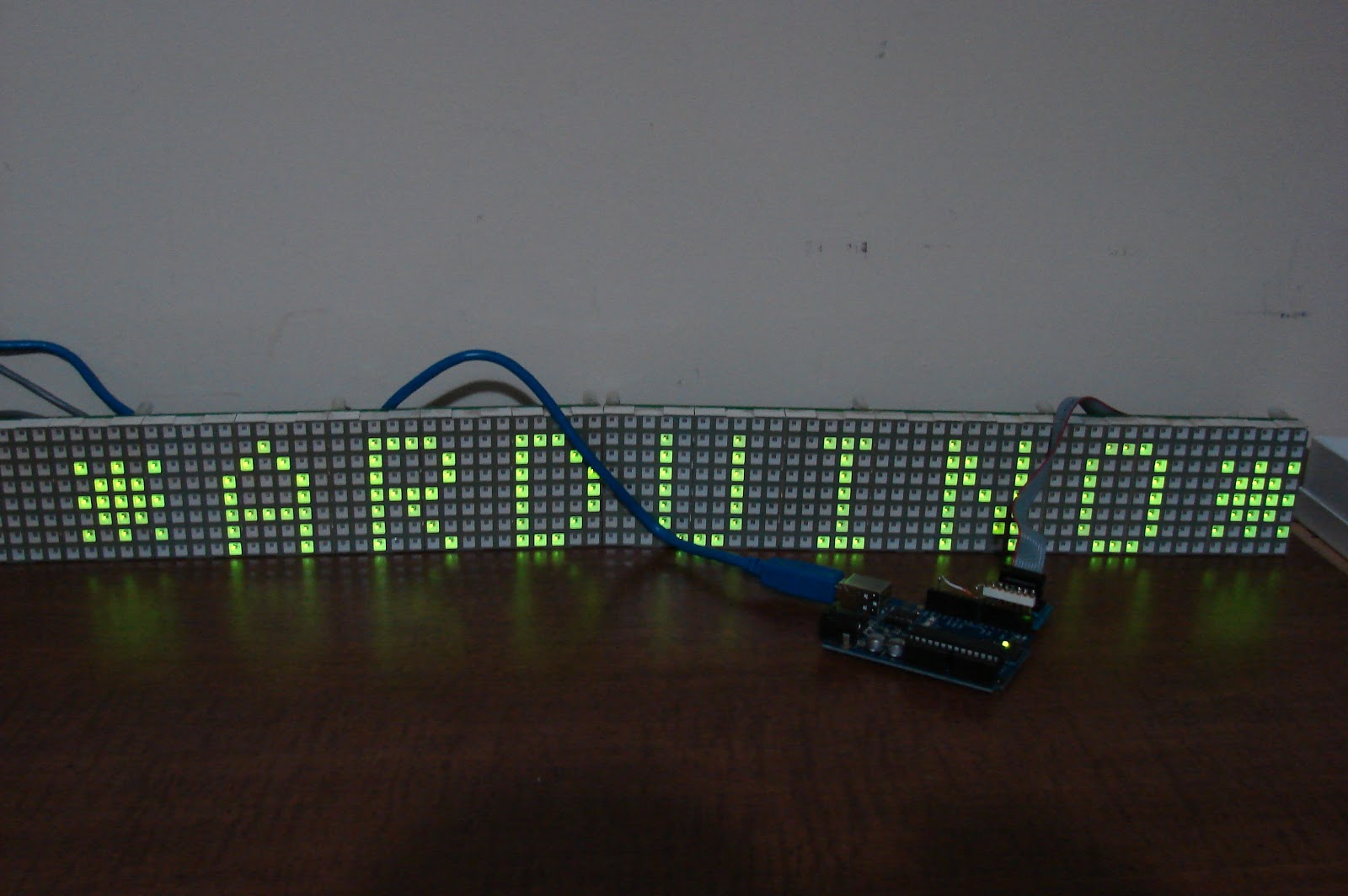
  char msg[] = "AR U NO LED SIGN ";  
  char gmsg[] = "A D I O LED SIGN ";
  for (int charIndex=0; charIndex < (sizeof(msg)-1); charIndex++)
  {
    int alphabetIndex = msg[charIndex] - '@';
    int galphabetIndex = gmsg[charIndex] - '@';
    if (alphabetIndex < 0) alphabetIndex = 0;
    if (galphabetIndex < 0) galphabetIndex = 0;
    //-- Draw one character of the message --
    for (int col = 0; col < 6; col++)
    {
      for (int row = 0; row < 8; row++)
      {
        // Set the pixel to the alphabet for columns 0 thru 4
        bool isOn = 0;
        if (col<5) isOn = bitRead( alphabets[alphabetIndex][col], 7-row ) == 1;
        Plot( numCols-1, row, isOn); 
        isOn = 0;
        if (col<5) isOn = bitRead( alphabets[galphabetIndex][col], 7-row ) == 1;
        GPlot( numCols-1, row, isOn); 
      }
      //-- The more times you repeat this loop, the slower we would scroll --
      for (int refreshCount=0; refreshCount < 50; refreshCount++)
        RefreshDisplay();
      //-- Shift the bitmap one column to left --
      for (int row=0; row<8; row++) //right shift
      {
        for (int zone=0; zone < numZones; zone++)
        {
          // This right shift would show a left scroll on display.
          bitmap[row][zone] = bitmap[row][zone] >> 1;  //right shift
          gbitmap[row][zone] = gbitmap[row][zone] >> 1;  //right shift
          // Roll over lowest bit from the next zone as highest bit of this zone.
          if (zone < maxZoneIndex) bitWrite(bitmap[row][zone], 7, bitRead(bitmap[row][zone+1], 0));
          if (zone < maxZoneIndex) bitWrite(gbitmap[row][zone], 7, bitRead(gbitmap[row][zone+1], 0));
        }
      }
    }
  }
} 
//=== L O O P ===
void loop() {
  AlphabetSoup();
} 

Silent Radio LED sign to Arduino Continued


I am playing with the Silent Radio LED sign once again.  There are two problems to fix, the brightness and the scrolling. 

See a Sunrise Systems sign converted with newer software at:   https://bobdavis321.blogspot.com/2019/04/arduino-uno-interfaced-to-sunrise.html

Working on the brightness problem, I know that the 4017 design did not work well because there was no way to turn off the sign while updating the shift registers.  As a result I went back to having the Arduino directly drive the TIP120 drivers.  Another possible solution might be to use an ULN2003’s as a level shifter.  That would require a 6 or 7 volt power supply as well.  I wanted to stay with a 5 volt power supply.  I have observed that the Cadaces modules use 22 ohm current limiting resistors.  The Silent Radio signs use 100 ohm resistors.  Maybe changing the resistors is a better solution?  Here is the schematic.
 This is what it looks like, the Arduino is underneath the circuit board.

On the scrolling issue, I have suspects that the sign scrolls backwards because it is upside down.  So I changed two lines of code so the sigh would work upside down and viola, it works.  It now scrolls from right to left like it should have been doing.

Here is the code to make it work.
//**************************************************************//
//  Name    : Silent Radio Driver                               //
//  Author  : Bob Davis                                         //
//  Date    : 25 April, 2011                                    //
//  Version : 1.0                                               //
//  Based on work of Hari Wiguna - http://g33k.blogspot.com/    //
//****************************************************************
// Pins for the row drivers
int row1Pin = 1;
int row2Pin = 2;
int row3Pin = 3;
int row4Pin = 4;
int row5Pin = 5;
int row6Pin = 6;
int row7Pin = 7;

// Pins for column shift registers
int clockPin = 8;
int dataPin = 9;

// Set the pins to output to the circuit
void setup() {
  pinMode(clockPin, OUTPUT);
  pinMode(dataPin, OUTPUT);
  pinMode(row1Pin, OUTPUT);
  pinMode(row2Pin, OUTPUT);
  pinMode(row3Pin, OUTPUT);
  pinMode(row4Pin, OUTPUT);
  pinMode(row5Pin, OUTPUT);
  pinMode(row6Pin, OUTPUT);
  pinMode(row7Pin, OUTPUT);
}

//=== B I T M A P ===
//Bits in this array represents one LED of the matrix
// 8 is # of rows, 7 is # of LED matrix we have
byte bitmap[8][12]; // Change the 7 to however many matrices you want to use.
int numZones = sizeof(bitmap) / 8; 
// I will refer to each group of 8 columns (represented by one matrix) as a Zone.
int maxZoneIndex = numZones-1;
int numCols = numZones * 8;

//=== F O N T ===
// Font courtesy of aspro648
// http://www.arduino.cc/cgi-bin/yabb2/YaBB.pl?num=1203747843/22
// First char is @, next is A, B, etc.  Only lower case, no symbols.  
// The @ will display as space character.
byte alphabets[][5] = {
  {0,0,0,0,0},
  {31, 36, 68, 36, 31},
  {127, 73, 73, 73, 54},
  {62, 65, 65, 65, 34},
  {127, 65, 65, 34, 28},
  {127, 73, 73, 65, 65},
  {127, 72, 72, 72, 64},
  {62, 65, 65, 69, 38},
  {127, 8, 8, 8, 127},
  {0, 65, 127, 65, 0},
  {2, 1, 1, 1, 126},
  {127, 8, 20, 34, 65},
  {127, 1, 1, 1, 1},
  {127, 32, 16, 32, 127},
  {127, 32, 16, 8, 127},
  {62, 65, 65, 65, 62},
  {127, 72, 72, 72, 48},
  {62, 65, 69, 66, 61},
  {127, 72, 76, 74, 49},
  {50, 73, 73, 73, 38},
  {64, 64, 127, 64, 64},
  {126, 1, 1, 1, 126},
  {124, 2, 1, 2, 124},
  {126, 1, 6, 1, 126},
  {99, 20, 8, 20, 99},
  {96, 16, 15, 16, 96},
  {67, 69, 73, 81, 97},
};

//=== F U N C T I O N S ===
// This routine takes whatever we've setup in the bitmap array and display it on the matrix
void RefreshDisplay()
{
  for (int row = 0; row < 8; row++) {
    //-- turn off the display --
    digitalWrite(row1Pin, LOW);  
    digitalWrite(row2Pin, LOW);  
    digitalWrite(row3Pin, LOW);  
    digitalWrite(row4Pin, LOW);  
    digitalWrite(row5Pin, LOW);  
    digitalWrite(row6Pin, LOW);  
    digitalWrite(row7Pin, LOW); 
    //-- Shift out to each matrix (zone is 8 columns represented by one matrix)
    for (int zone = maxZoneIndex; zone >= 0; zone--) {
      shiftOut(dataPin, clockPin, MSBFIRST, bitmap[row][zone]);
    }

    //-- turn the current row on --
    if (row == 1) digitalWrite (row7Pin, HIGH);  
    if (row == 2) digitalWrite (row6Pin, HIGH);  
    if (row == 3) digitalWrite (row5Pin, HIGH);  
    if (row == 4) digitalWrite (row4Pin, HIGH);  
    if (row == 5) digitalWrite (row3Pin, HIGH);  
    if (row == 6) digitalWrite (row2Pin, HIGH);  
    if (row == 7) digitalWrite (row1Pin, HIGH);  

    //-- Wait a little bit to let humans see what we've pushed out onto the matrix --
    delayMicroseconds(500);
  }
}

// Converts row and colum to actual bitmap bit and turn it off/on
void Plot(int col, int row, bool isOn)
{
  int zone = col / 8;
  int colBitIndex = col % 8;
  byte colBit = 1 << colBitIndex;
  if (isOn)
    bitmap[row][zone] =  bitmap[row][zone] | colBit;
  else
    bitmap[row][zone] =  bitmap[row][zone] & (~colBit);
}

// Plot each character of the message one column at a time, updated the display, shift bitmap left.
void AlphabetSoup()
{
  char msg[] = "ARDUINO LED SIGN ";
  for (int charIndex=0; charIndex < (sizeof(msg)-1); charIndex++)
  {
    int alphabetIndex = msg[charIndex] - '@';
    if (alphabetIndex < 0) alphabetIndex=0;
    //-- Draw one character of the message --
    // Each character is only 5 columns wide
    for (int col = 0; col < 6; col++)
    {
      for (int row = 0; row < 8; row++)
      {
        // Set the pixel to the alphabet for columns 0 thru 4
        bool isOn = 0;
        if (col<5 --="" 1="" 50="" 7-row="" alphabetindex="" alphabets="" bitmap="" col="" column="" for="" int="" ison="" left="" loop="" more="" numcols-1="" one="" plot="" refreshcount="" refreshdisplay="" repeat="" row="" scroll="" shift="" slower="" the="" this="" times="" to="" we="" would="" you="" zone=""> 0; zone--)
        for (int zone=0; zone < numZones; zone++)
        {
          // This right shift would show a left scroll on display.
          bitmap[row][zone] = bitmap[row][zone] >> 1;
          
          // Roll over lowest bit from the next zone as highest bit of this zone.
          if (zone < maxZoneIndex) bitWrite(bitmap[row][zone], 7, bitRead(bitmap[row][zone+1],0));
        }
      }
    }
  }
} 
//=== L O O P ===
void loop() {
  AlphabetSoup();
} 


Wednesday, April 24, 2013

16 by 40 Dual color LED sign being sold on eBay by RDR Electronics.

They are advertising this sign as "10 - LED 8x8 5mm Dot Matrix Array Module Common Anode Red & Green 60mm".  The sign has a two pin power connector and a six pin pass through connector.  The pass through connector comes in on the right and leaves on the left.  The six signals pass through two 4049's on the way through the board.

Here is a picture of the back of the sign.  WO/32779/1 might mean something to someone?

 Here is a picture of the front side of the sign:

The six pin connector on the right has pin one at the top, here is what they connect to:
1 - CD4094 Pin 3 Clock top row.
2 - CD4094 Pin 15 Output Enable for all 4094's (And bottom 4015 pin 7 as data)
3 - CD4094 Pin 2 Serial Data bottom row
4 - CD4094 Pin 1 Strobe for all 4094's (And both 4015 pin 9 and 1 as clock)
5 - CD4094 Pin 2 Serial Data top row
6 - CD4094 Pin 3 Clock bottom row

CD4094 Eight bit shift registers are used throughout the sign.  They then used TD62083 drivers to drive the sign.  I do not know how it drives the rows as the CD4094's only are used for the columns.  There are some CD4015's that appear to be used for the rows.  The next step is to interface it to a Arduino.

You might notice that there are no references to the row selection hardware.  I have tried to get the sign working, but then I took it all back apart to trace out some more runs.  Here is what I found.  Pin 2 goes to the 4049's pin 15 as "output enable", but it also goes to the bottom 4015A pin 7 as "Data".  Pin 4 goes to the 4049's Pin 1 as "strobe" but it also goes to both 4015's pin 9 and 1 as "Clock".

Here I am working on it.  It may not run off a 5 volt 2.5V AC adapter, it needs more power!
*** Update - it works on 5 volts at 2.5 amps when displaying text ***


Tuesday, April 23, 2013

Dell Inspiron Ultrabook 14Z Hard drive removal

Recently I had the fun of removing the hard drive from a Dell Inspiron Ultrabook 14Z.  The hard drive is located under the battery.  Where is the battery you may ask??

First you need to remove the memory cover and the memory modules.  Under one of the memory modules is a hidden screw.  With that screw removed you can remove the keyboard by pushing up on the three clips at the top of the keyboard.

Once the memory cover is removed the CD ROM is free to be removed as well.  There is one screw above the CD ROM that has to be removed. 


There are seven screws under plastic covers underneath the laptop and four screws under the keyboard that need to be removed.  Three are near the front edge and one is near the CPU fan as seen in the picture below.

Next release the four ribbon cables.  Then the top cover comes off by releasing catches all around the edges.  Now you can see the battery.  There are two screws holding the battery in.  The hard drive is then reachable.

Monday, April 22, 2013

Removing the CNet Download virus

Recently while working on a website, I noticed that some words were being underlined.  I did not make them links so I scrolled over the words and this popped up:

I immediately realized that I had a virus in my computer.  What on earth does "Sermons" have to do with eating bananas?  What total nonsense?  I tried scanning my computer with MSE and MBAM to no avail.  So I went to add/remove programs and there it was "GetSavin".  It easily removed itself that way. 

I did some research and this virus comes from going to download.com (download.cnet.com) and they install it on your computer. There was the day when I trusted download.com, I have long since learned to steer clear of them.  They install things on your computer without your permission and then activate it whenever they want.

Wednesday, April 17, 2013

My new book called "Arduino LED Projects"

I have been working on a new book called "Arduino LED Projects".  Now I am looking for a publisher.  It has a dozen projects from electronic dice, to a "wheel of prizes", to a quiz lockout machine, to a meter, and even a 8 by 8 dual color LED array.  It is already listed on Amazon.com.

Here is a picture of the table of contents:


This is a peak at one of the pages:


Here is a picture of the front cover:


Here I am playing with one of the projects, a two digit meter:

Monday, April 15, 2013

Signature Electronic Sign to Arduino Adapter Part who knows?

I have not given up on the idea of using an Arduino to power a 120 by 32 LED sign.  In fact I have it working, but the Arduino is still not fast enough.  The display flickers.  I made a quick adapter by taking the old controller and cutting the jacks off the circuit board.  Then I soldered a header onto it so that it plugs into the Arduino.  Here is what the adapter looks like;

Here is what it looks like when it is working:

Here is the code to make it work.  I got rid of the "Shift out" command, each shift clock sends eight bits to the signs eight shift registers.  That makes it run much faster.
//**********************************
//  Name    : 120x32 Cadaces Driver                         
//  Author  : Bob Davis                                  
//  Date    : 23 February, 2013                          
//  Version : 1.0                                        
//**********************************
// Pins for the row drivers
int row1Pin = 2;    //R1
int row2Pin = 7;    //R2
int row3Pin = 1;    //R3
int rowEnable = 8;    //REN
int rclockPin = 6;    //RCK
int clockPin = 3;     //SCK
int dataPin = 5;     //RSD
int gdataPin = 4;      //GSD
int dataPin1 = 9;     //RSD
int gdataPin1 = 10;      //GSD
int dataPin2 = 12;     //RSD
int gdataPin2 = 11;      //GSD
int dataPin3 = 13;     //RSD
int gdataPin3 = 14;      //GSD

// Set the pins to output to the sign
void setup() {
  pinMode(row1Pin, OUTPUT);
  pinMode(row2Pin, OUTPUT);
  pinMode(row3Pin, OUTPUT);
  pinMode(rowEnable, OUTPUT);
  pinMode(rclockPin, OUTPUT);
  pinMode(clockPin, OUTPUT);
  pinMode(dataPin, OUTPUT);
  pinMode(gdataPin, OUTPUT);
  pinMode(dataPin1, OUTPUT);
  pinMode(gdataPin1, OUTPUT);
  pinMode(dataPin2, OUTPUT);
  pinMode(gdataPin2, OUTPUT);
  pinMode(dataPin3, OUTPUT);
  pinMode(gdataPin3, OUTPUT);
}
//=== Character Array ===
// Characters are A, B, C, etc.  Only upper case. 
byte alphabets[][8] = {
  {0, 04, 10, 17, 17, 31, 17, 17}, //A
  {0, 30, 17, 17, 30, 17, 17, 30}, //B
  {0, 14, 17, 16, 16, 16, 17, 14}, //C
  {0, 28, 18, 17, 17, 17, 18, 28}, //D
  {0, 31, 16, 16, 31, 16, 16, 31}, //E
  {0, 31, 16, 16, 31, 16, 16, 16}, //F
  {0, 14, 17, 16, 16, 19, 17, 14}, //G
  {0, 17, 17, 17, 31, 17, 17, 17}, //H
  {0, 14, 04, 04, 04, 04, 04, 14}, //I
  {0, 07, 02, 02, 02, 02, 10, 14}, //J
  {0, 17, 18, 20, 24, 20, 18, 17}, //K
  {0, 16, 16, 16, 16, 16, 16, 31}, //L
  {0, 10, 21, 21, 21, 17, 17, 17}, //M
  {0, 17, 25, 25, 21, 19, 19, 17}, //N
  {0, 14, 17, 17, 17, 17, 17, 14}, //O
  {0, 30, 17, 17, 30, 16, 16, 16}, //P
  {0, 14, 17, 17, 17, 17, 19, 15}, //Q
  {0, 30, 17, 17, 30, 20, 18, 17}, //R
  {0, 14, 17, 16, 14, 01, 17, 14}, //S
  {0, 31, 04, 04, 04, 04, 04, 04}, //T
  {0, 17, 17, 17, 17, 17, 17, 14}, //U
  {0, 17, 17, 17, 10, 10, 10, 04}, //V
  {0, 17, 17, 17, 21, 21, 21, 10}, //W
  {0, 17, 17, 10, 04, 10, 17, 17}, //X
  {0, 17, 10, 10, 04, 04, 04, 04}, //Y
  {0, 31, 8, 04, 02, 04, 8, 31}, //Z
  {0, 0, 21, 14, 31, 14, 21, 0}, //*
};
byte numbers[][8] = {
  {0, 04, 12, 04, 04, 04, 04, 14}, //1
  {0, 14, 17, 01, 02, 04, 8, 31}, //2
  {0, 14, 01, 01, 06, 01, 01, 14}, //3
  {0, 17, 17, 17, 31, 01, 01, 01}, //4
  {0, 31, 16, 16, 14, 01, 17, 14}, //5
  {0, 14, 16, 16, 30, 17, 17, 14}, //6
  {0, 31, 01, 01, 02, 04, 8, 16}, //7
  {0, 14, 17, 17, 14, 17, 17, 14}, //8
  {0, 14, 17, 17, 15, 01, 01, 01}, //9
  {0, 14, 17, 17, 17, 17, 17, 14}, //0
};
byte bitmap[][8] = {  //red characters
  {0, 0,0,0,0,0,0,0},
  {0, 04, 12, 04, 04, 04, 04, 14}, //1
  {0, 14, 17, 01, 02, 04, 8, 31}, //2
  {0, 14, 17, 17, 17, 17, 17, 14}, //0
  {0, 17, 17, 10, 04, 10, 17, 17}, //X
  {0, 14, 01, 01, 06, 01, 01, 14}, //3
  {0, 14, 17, 01, 02, 04, 8, 31}, //2
  {0, 0,0,0,0,0,0,0},
  {0,  4, 10, 17, 17, 31, 17, 17}, //A
  {0, 0,0,0,0,0,0,0},
  {0, 28, 18, 17, 17, 17, 18, 28}, //D
  {0, 0,0,0,0,0,0,0},
  {0, 14, 04, 04, 04, 04, 04, 14}, //I
  {0, 17, 25, 25, 21, 19, 19, 17}, //N
  {0, 14, 17, 17, 17, 17, 17, 14}, //O
  {0, 0,0,0,0,0,0,0},
  {0, 14, 17, 16, 14, 01, 17, 14}, //S
  {0, 14, 04, 04, 04, 04, 04, 14}, //I
  {0, 14, 17, 16, 16, 19, 17, 14}, //G
  {0, 17, 25, 25, 21, 19, 19, 17}, //N
  {0, 0,0,0,0,0,0,0},
};
byte gbitmap[][8] = {  //green characters
  {0, 0,0,0,0,0,0,0},
  {0, 04, 12, 04, 04, 04, 04, 14}, //1
  {0, 14, 17, 01, 02, 04, 8, 31}, //2
  {0, 14, 17, 17, 17, 17, 17, 14}, //0
  {0, 17, 17, 10, 04, 10, 17, 17}, //X
  {0, 14, 01, 01, 06, 01, 01, 14}, //3
  {0, 14, 17, 01, 02, 04, 8, 31}, //2
  {0, 0,0,0,0,0,0,0},
  {0,  4, 10, 17, 17, 31, 17, 17}, //A
  {0, 30, 17, 17, 30, 20, 18, 17}, //R
  {0, 0,0,0,0,0,0,0},
  {0, 17, 17, 17, 17, 17, 17, 14}, //U
  {0, 14, 04, 04, 04, 04, 04, 14}, //I
  {0, 0,0,0,0,0,0,0},
  {0, 14, 17, 17, 17, 17, 17, 14}, //O
  {0, 0,0,0,0,0,0,0},
  {0, 14, 17, 16, 14, 01, 17, 14}, //S
  {0, 14, 04, 04, 04, 04, 04, 14}, //I
  {0, 14, 17, 16, 16, 19, 17, 14}, //G
  {0, 17, 25, 25, 21, 19, 19, 17}, //N
  {0, 0,0,0,0,0,0,0},
};
void RunSign(){
  for (int row = 7; row > 0; row--) {
    // turn off display
    digitalWrite(rowEnable, HIGH);
    digitalWrite(rclockPin, LOW);
    // send serial data to display 20 = number of characters
    for (int character = 0; character < 21; character++){
     for (int shiftbit = 5; shiftbit > -1; shiftbit--){
      digitalWrite(gdataPin, LOW);
      digitalWrite(dataPin, LOW);
      digitalWrite(gdataPin1, LOW);
      digitalWrite(dataPin1, LOW);
      digitalWrite(gdataPin2, LOW);
      digitalWrite(dataPin2, LOW);
      digitalWrite(gdataPin3, LOW);
      digitalWrite(dataPin3, LOW);
      if bitRead(gbitmap[character][row],shiftbit) digitalWrite(gdataPin, HIGH);
      if bitRead(bitmap[character][row],shiftbit) digitalWrite(dataPin, HIGH);
      if bitRead(gbitmap[character][row],shiftbit) digitalWrite(gdataPin1, HIGH);
      if bitRead(bitmap[character][row],shiftbit) digitalWrite(dataPin1, HIGH);
      if bitRead(gbitmap[character][row],shiftbit) digitalWrite(gdataPin2, HIGH);
      if bitRead(bitmap[character][row],shiftbit) digitalWrite(dataPin2, HIGH);
      if bitRead(gbitmap[character][row],shiftbit) digitalWrite(gdataPin3, HIGH);
      if bitRead(bitmap[character][row],shiftbit) digitalWrite(dataPin3, HIGH);
      digitalWrite(clockPin, HIGH);
      digitalWrite(clockPin, LOW);
    } }
    //latch the data
    digitalWrite(rclockPin, HIGH);
    // set up 74138 row sesection and turn display back on
    digitalWrite(row1Pin, LOW);
    digitalWrite(row2Pin, LOW);
    digitalWrite(row3Pin, LOW);
    if bitRead(row,0) digitalWrite (row1Pin, HIGH);
    if bitRead(row,1) digitalWrite (row2Pin, HIGH);
    if bitRead(row,2) digitalWrite (row3Pin, HIGH);
    digitalWrite(rowEnable, LOW);
    // Wait to see what we sent to the display ;
    delayMicroseconds(500);
  }


//=== L O O P ===
void loop() {
  RunSign();
}

How to make a quick Arduino to Cadaces adapter.


Some people asked me for a simpler way to interface the Cadaces modules to an Arduino, so here it is!

All you need to do this is a five pin header and four jumper wires.  Insert the five pin header into D1 through D5.  Then plug the cable from the display into those five pins so the other five pins hang off to the right.  Add the four jumper wires according to the schematic.
 Here is a picture of the quick adapter in operation.  The green wire if 5 volts going to power the sign.

Here are the pin number changes to the code to make it work;

// Pins for the row drivers
int row1Pin = 2;            //R1
int row2Pin = 7;            //R2
int row3Pin = 1;            //R3
int rowEnable = 8;        //REN
int rclockPin = 6;          //RCK
int clockPin = 3;           //SCK
int dataPin = 5;             //RSD
int gdataPin = 4;           //GSD

Here is the total code for 8 x 40 array:

//**********************************
//  Name    : Cadaces Driver                         
//  Author  : Bob Davis                                  
//  Date    : 23 February, 2013                                 
//  Version : 1.0                                             
//**********************************
// Pins for the row drivers
int row1Pin = 2;         //R1
int row2Pin = 7;         //R2
int row3Pin = 1;         //R3
int rowEnable = 8;     //REN
int rclockPin = 6;        //RCK
int clockPin = 3;         //SCK
int dataPin = 5;          //RSD
int gdataPin = 4;        //GSD
// Set the pins to output to the sign
void setup() {
  pinMode(row1Pin, OUTPUT);
  pinMode(row2Pin, OUTPUT);
  pinMode(row3Pin, OUTPUT);
  pinMode(rowEnable, OUTPUT);
  pinMode(rclockPin, OUTPUT);
  pinMode(clockPin, OUTPUT);
  pinMode(dataPin, OUTPUT);
  pinMode(gdataPin, OUTPUT);
}
byte bitmap[][8] = {  //red characters
  {0, 0,0,0,0,0,0,0},
  {0,  4, 10, 17, 17, 31, 17, 17}, //A
  {0, 30, 17, 17, 30, 20, 18, 17}, //R
  {0, 28, 18, 17, 17, 17, 18, 28}, //D
  {0, 0,0,0,0,0,0,0},
  {0, 14, 04, 04, 04, 04, 04, 14}, //I
  {0, 17, 25, 25, 21, 19, 19, 17}, //N
  {0, 14, 17, 17, 17, 17, 17, 14}, //O
  {0, 0,0,0,0,0,0,0},
};
byte gbitmap[][8] = {  //green characters
  {0, 0,0,0,0,0,0,0},
  {0,  4, 10, 17, 17, 31, 17, 17}, //A
  {0, 30, 17, 17, 30, 20, 18, 17}, //R
  {0, 0,0,0,0,0,0,0},
  {0, 17, 17, 17, 17, 17, 17, 14}, //U
  {0, 14, 04, 04, 04, 04, 04, 14}, //I
  {0, 0,0,0,0,0,0,0},
  {0, 14, 17, 17, 17, 17, 17, 14}, //O
  {0, 0,0,0,0,0,0,0},
};
void RunSign(){
  for (int row = 7; row > 0; row--) {
    // turn off display
    digitalWrite(rowEnable, HIGH);
    digitalWrite(rclockPin, LOW);
    // send serial data to display 8 = number of characters
    for (int character = 0; character < 8; character++){
     for (int shiftbit = 5; shiftbit > -1; shiftbit--){
      digitalWrite(gdataPin, LOW);
      digitalWrite(dataPin, LOW);
      if bitRead(gbitmap[character][row],shiftbit) digitalWrite(gdataPin, HIGH);
      if bitRead(bitmap[character][row],shiftbit) digitalWrite(dataPin, HIGH);
      digitalWrite(clockPin, HIGH); digitalWrite(clockPin, LOW);
    } }
    //latch the data
    digitalWrite(rclockPin, HIGH);
    // set up 74138 row selection and turn display back on
    digitalWrite(row1Pin, LOW);
    digitalWrite(row2Pin, LOW);
    digitalWrite(row3Pin, LOW);
    if bitRead(row,0) digitalWrite (row1Pin, HIGH);
    if bitRead(row,1) digitalWrite (row2Pin, HIGH);
    if bitRead(row,2) digitalWrite (row3Pin, HIGH);
    digitalWrite(rowEnable, LOW);
    // Wait to see what we sent to the display ;
    delayMicroseconds(500);
  }
} 

//=== L O O P ===
void loop() {
  RunSign();
}

Wednesday, March 27, 2013

Dell Inspiron 1501 1505 Hinge and LCD Bracket repair

I have become a fan of the Dell Inspiron 1501 and 1503 laptops. I first fixed up one for a friend. Then someone gave me one for free. I cleaned out the cooling fan and replaced the keyboard and now it is my main computer. Recently I purchased two Dell E1505 laptops for $40 each. Their hinges were completely broken and one of the screens was even damaged because of the hinge problem. You can buy a hinge/LCD bracket assembly on eBay, or you can fix it yourself.

To fix it yourself remove the rubber stops and the screws that are located behind them. Remove the front bezel. Optionally remove the plastic over that is at the top of the keyboard to expose the bottoms of the hinges. Remove the broken hinge mounts, you should now see what is in the picture below.

To modify it first use a 1/4 inch drill bit to remove any burs on the three holes that are behind each hinge mounting bracket, so that the bracket will now fit flush against the aluminum behind it. Then use a 5/64 inch drill bit to drill the top hole in the bracket right through the back cover. Next, from the back side, drill a 3/32 inch hole through the cover and the aluminum, but NOT into the hinge bracket. Next put a screw into the new hole and thread it into the hinge mounting bracket. Before tightening that screw, you can optionally put a drop of glue or epoxy behind the bracket and then quickly tighten the screw.


If everything goes well the bracket is now glued and screwed back into place. Do not use extra super glue, the fumes off it can glue everything together and even melt plastic nearby. A tiny drop is all that is needed. I have done this repair without using any glue and it works fine.

While you are in there be sure to take out the cooling fan and clean off the heat exchanger!

Thursday, March 7, 2013

Mini Cadaces 8 by 10 LED to Arduino

I have written some code to work with the small 8 by 10 LED array boards made by Cadaces/Signature Electronic signs.  Here is a picture of one of them working:
Here is the code for the Arduino to make it work, the interface is that same as was used in previous posts.


//****************************************************//
//  Name    : Cadaces Driver                          //
//  Author  : Bob Davis                               //
//  Date    : 23 February, 2013                       //
//  Version : 1.0                                     //
//****************************************************//
// Pins for the row drivers
int row1Pin = 1;
int row2Pin = 2;
int row3Pin = 3;
int rowEnable = 4;
int rclockPin = 5;
int clockPin = 6;
int dataPin = 7;
int gdataPin = 8;
// Set the pins to output to the sign
void setup() {
  pinMode(row1Pin, OUTPUT);
  pinMode(row2Pin, OUTPUT);
  pinMode(row3Pin, OUTPUT);
  pinMode(rowEnable, OUTPUT);
  pinMode(rclockPin, OUTPUT);
  pinMode(clockPin, OUTPUT);
  pinMode(dataPin, OUTPUT);
  pinMode(gdataPin, OUTPUT);
}

//=== Character Array ===
// Characters are A, B, C, etc.  Only upper case, no symbols. 
byte alphabets[][8] = {
  {0, 04, 10, 17, 17, 31, 17, 17}, //A
  {0, 30, 17, 17, 30, 17, 17, 30}, //B
  {0, 14, 17, 16, 16, 16, 17, 14}, //C
  {0, 28, 18, 17, 17, 17, 18, 28}, //D
  {0, 31, 16, 16, 31, 16, 16, 31}, //E
  {0, 31, 16, 16, 31, 16, 16, 16}, //F
  {0, 14, 17, 16, 16, 19, 17, 14}, //G
  {0, 17, 17, 17, 31, 17, 17, 17}, //H
  {0, 14, 04, 04, 04, 04, 04, 14}, //I
  {0, 07, 02, 02, 02, 02, 10, 14}, //J
  {0, 17, 18, 20, 24, 20, 18, 17}, //K
  {0, 16, 16, 16, 16, 16, 16, 31}, //L
  {0, 10, 21, 21, 21, 17, 17, 17}, //M
  {0, 17, 25, 25, 21, 19, 19, 17}, //N
  {0, 14, 17, 17, 17, 17, 17, 14}, //O
  {0, 30, 17, 17, 30, 16, 16, 16}, //P
  {0, 14, 17, 17, 17, 17, 19, 15}, //Q
  {0, 30, 17, 17, 30, 20, 18, 17}, //R
  {0, 14, 17, 16, 14, 01, 17, 14}, //S
  {0, 31, 04, 04, 04, 04, 04, 04}, //T
  {0, 17, 17, 17, 17, 17, 17, 14}, //U
  {0, 17, 17, 17, 10, 10, 10, 04}, //V
  {0, 17, 17, 17, 21, 21, 21, 10}, //W
  {0, 17, 17, 10, 04, 10, 17, 17}, //X
  {0, 17, 10, 10, 04, 04, 04, 04}, //Y
  {0, 31, 8, 04, 02, 04, 8, 31}, //Z
  {0, 0, 21, 14, 31, 14, 21, 0}, //*
};
byte bitmap[][8] = {  //red characters
  {0, 0,0,0,0,0,0,0},
  {0, 17, 17, 17, 31, 17, 17, 17}, //H
};
byte gbitmap[][8] = { //green characters
  {0, 14, 04, 04, 04, 04, 04, 14}, //I
  {0, 0,0,0,0,0,0,0},
};
void RunSign()
{
  for (int row = 7; row > 0; row--)
  {
    // turn off display
    digitalWrite(rowEnable, HIGH);
    digitalWrite(rclockPin, LOW);
    // send serial data to display 2 = number of characters
    for (int character = 0; character < 2; character++)
    {
      for (int shiftbit = 5; shiftbit >=0; shiftbit--){
    if bitRead(gbitmap[character][row],shiftbit) digitalWrite(gdataPin, HIGH);
else digitalWrite(gdataPin, LOW);
    if bitRead(bitmap[character][row],shiftbit) digitalWrite(dataPin, HIGH);
else digitalWrite(dataPin, LOW);
    digitalWrite(clockPin, HIGH); digitalWrite(clockPin, LOW);
      }
    }
    //latch the data
    digitalWrite(rclockPin, HIGH);
    // set up 74138 row sesection and turn display back on
    if bitRead(row,0) digitalWrite (row1Pin, HIGH); else digitalWrite(row1Pin, LOW); 
    if bitRead(row,1) digitalWrite (row2Pin, HIGH); else digitalWrite(row2Pin, LOW);
    if bitRead(row,2) digitalWrite (row3Pin, HIGH); else digitalWrite(row3Pin, LOW);
    digitalWrite(rowEnable, LOW);
    // Wait to see what we sent to the display ;
    delayMicroseconds(500);
  }


//=== L O O P ===
void loop() {
  RunSign();
}

Friday, March 1, 2013

Dunlap Clarke Rebuild part 3

A while back I rebuilt a Dunlap-Clark amplifier using some TDA7294 modules.  I was disappointed with the anemic results of about 150 watts per channel.  I searched eBay and found a pre-assembled circuit that claimed about 350 watts per channel.  They advertise it as "1PC L20 350W Mono Audio Power Amplifier Kit AMP Board".

Here are the specifications:
    Power 200W (8R) 350W (4R)
    Voltage: DC + - 45V
    Rectified AC voltage range AC 12V to AC dual dual 32V;
    THD = 0.009% 1K HZ 50W 8R
    SR = 35V / US
    Noise 92DBU
    EIN = 114 DB
    Frequency Response 20-20KHZ + - 0.5 DB
    34 times the voltage gain
    All resistors are 1% precision high precision resistors
    PCB size: 116MM * 72 MM*1.6MM
    All capacitors are imported original. 
    KEC original imported audio power tube.
    Promote the use of KEC B817 D1047 and Toshiba A1930 C5171
    Package including: 1X L20 Mono Amplifier Board

You might note that the specifications are very poor translations. The big shock to me was the price, it was only $17.50 plus $7 shipping.  That is less than the cost of two of the old TO-3 metal power transistors! The circuit board does not come with a heat sink, and the transistors certainly do not fit the old TO-3 power transistor holes.  So I made a "heat sink adapter" out of a piece of aluminum.

Here is what it looks like mounted inside the Dunlap Clark Cabinet:I am still using the 50 volt center tapped power transformer although the board can use up to 62 volts center tapped.
Next I need to add a bridge rectifier and some filter caps so I can start testing it out.

I connected the power supply and it works.  I am limited to about 150 watts by the 1 volt output of the signal generator program running on my laptop.  That 1 volt input produces 25 volts peak to peak into 4 ohms with this setup.

Wednesday, February 27, 2013

Dual Color Cadaces modules to Arduino

I have obtained several dual color Cadaces modules. I will be selling them on eBay soon. Here is a sign in red:
Here it is again this time in green. The green is not as bright as the red.
Here it is with both colors alternating.  They do not work correctly because the Arduino serial out does not support sending both the red and green data using the same clock.  What happens is the right most part of the previous color is dragged through the background.
Here is a picture of the working sign.  It was taken with my phone camera so the quality is lacking.  I wrote my own version of the serial output to support different data for red and green to get it to work.


Here is a better picture of the working sign.

Here is an updated schematic with the addition of "GSD" or Green Serial Data.


Here is the dual color code, note that I replaced serialout with my own code to do the same job:


//****************************************************//
//  Name    : Color Cadaces Driver                          //
//  Author  : Bob Davis                               //
//  Date    : 23 February, 2013                       //
//  Version : 1.0                                     //
//****************************************************//
// Pins for the row drivers
int row1Pin = 1;
int row2Pin = 2;
int row3Pin = 3;
int rowEnable = 4;
int rclockPin = 5;
int clockPin = 6;
int dataPin = 7;
int gdataPin = 8;
// Set the pins to output to the sign
void setup() {
  pinMode(row1Pin, OUTPUT);
  pinMode(row2Pin, OUTPUT);
  pinMode(row3Pin, OUTPUT);
  pinMode(rowEnable, OUTPUT);
  pinMode(rclockPin, OUTPUT);
  pinMode(clockPin, OUTPUT);
  pinMode(dataPin, OUTPUT);
  pinMode(gdataPin, OUTPUT);
}

//=== Character Array ===
// Characters are A, B, C, etc.  Only upper case, no symbols. 
byte alphabets[][8] = {
  {0, 04, 10, 17, 17, 31, 17, 17}, //A
  {0, 30, 17, 17, 30, 17, 17, 30}, //B
  {0, 14, 17, 16, 16, 16, 17, 14}, //C
  {0, 28, 18, 17, 17, 17, 18, 28}, //D
  {0, 31, 16, 16, 31, 16, 16, 31}, //E
  {0, 31, 16, 16, 31, 16, 16, 16}, //F
  {0, 14, 17, 16, 16, 19, 17, 14}, //G
  {0, 17, 17, 17, 31, 17, 17, 17}, //H
  {0, 14, 04, 04, 04, 04, 04, 14}, //I
  {0, 07, 02, 02, 02, 02, 10, 14}, //J
  {0, 17, 18, 20, 24, 20, 18, 17}, //K
  {0, 16, 16, 16, 16, 16, 16, 31}, //L
  {0, 10, 21, 21, 21, 17, 17, 17}, //M
  {0, 17, 25, 25, 21, 19, 19, 17}, //N
  {0, 14, 17, 17, 17, 17, 17, 14}, //O
  {0, 30, 17, 17, 30, 16, 16, 16}, //P
  {0, 14, 17, 17, 17, 17, 19, 15}, //Q
  {0, 30, 17, 17, 30, 20, 18, 17}, //R
  {0, 14, 17, 16, 14, 01, 17, 14}, //S
  {0, 31, 04, 04, 04, 04, 04, 04}, //T
  {0, 17, 17, 17, 17, 17, 17, 14}, //U
  {0, 17, 17, 17, 10, 10, 10, 04}, //V
  {0, 17, 17, 17, 21, 21, 21, 10}, //W
  {0, 17, 17, 10, 04, 10, 17, 17}, //X
  {0, 17, 10, 10, 04, 04, 04, 04}, //Y
  {0, 31, 8, 04, 02, 04, 8, 31}, //Z
  {0, 0, 21, 14, 31, 14, 21, 0}, //*
};
byte bitmap[][8] = {  //red characters
  {0, 0,0,0,0,0,0,0},
  {0,  4, 10, 17, 17, 31, 17, 17}, //A
  {0, 30, 17, 17, 30, 20, 18, 17}, //R
  {0, 28, 18, 17, 17, 17, 18, 28}, //D
  {0, 0,0,0,0,0,0,0},
  {0, 14, 04, 04, 04, 04, 04, 14}, //I
  {0, 17, 25, 25, 21, 19, 19, 17}, //N
  {0, 14, 17, 17, 17, 17, 17, 14}, //O
  {0, 0,0,0,0,0,0,0},
  {0, 14, 17, 16, 14, 01, 17, 14}, //S
  {0, 0,0,0,0,0,0,0},
  {0, 14, 17, 16, 16, 19, 17, 14}, //G
  {0, 17, 25, 25, 21, 19, 19, 17}, //N
  {0, 0,0,0,0,0,0,0},
};
byte gbitmap[][8] = {  //green characters
  {0, 0,0,0,0,0,0,0},
  {0,  4, 10, 17, 17, 31, 17, 17}, //A
  {0, 30, 17, 17, 30, 20, 18, 17}, //R
  {0, 0,0,0,0,0,0,0},
  {0, 17, 17, 17, 17, 17, 17, 14}, //U
  {0, 14, 04, 04, 04, 04, 04, 14}, //I
  {0, 0,0,0,0,0,0,0},
  {0, 14, 17, 17, 17, 17, 17, 14}, //O
  {0, 0,0,0,0,0,0,0},
  {0, 14, 17, 16, 14, 01, 17, 14}, //S
  {0, 14, 04, 04, 04, 04, 04, 14}, //I
  {0, 0,0,0,0,0,0,0},
  {0, 17, 25, 25, 21, 19, 19, 17}, //N
  {0, 0,0,0,0,0,0,0},
};
void RunSign()
{
  for (int row = 7; row > 0; row--)
  {
    // turn off display
    digitalWrite(rowEnable, HIGH);
    digitalWrite(rclockPin, LOW);
    // send serial data to display 14 = number of characters
    for (int character = 0; character < 14; character++)
    {
      for (int shiftbit = 5; shiftbit > -1; shiftbit--){
    if bitRead(gbitmap[character][row],shiftbit) digitalWrite(gdataPin, HIGH); else digitalWrite(gdataPin, LOW);
    if bitRead(bitmap[character][row],shiftbit) digitalWrite(dataPin, HIGH); else digitalWrite(dataPin, LOW);
    digitalWrite(clockPin, HIGH); digitalWrite(clockPin, LOW);
      }
    }
    //latch the data
    digitalWrite(rclockPin, HIGH);
    // set up 74138 row sesection and turn display back on
    if bitRead(row,0) digitalWrite (row1Pin, HIGH); else digitalWrite(row1Pin, LOW); 
    if bitRead(row,1) digitalWrite (row2Pin, HIGH); else digitalWrite(row2Pin, LOW);
    if bitRead(row,2) digitalWrite (row3Pin, HIGH); else digitalWrite(row3Pin, LOW);
    digitalWrite(rowEnable, LOW);
    // Wait to see what we sent to the display ;
    delayMicroseconds(500);
  }


//=== L O O P ===
void loop() {
  RunSign();
}

Wednesday, February 20, 2013

Signature Electronic LED Sign to Arduino part 4

*** BREAKING NEWS!!! ***  The next batch of Cadaces modules are RED and GREEN in color.  This will require an updated adapter and updated software.  More to come as soon as I get it working!

Here are some additional pictures of the Arduino to Cadaces adapter.  Hopefully these are clear enough so you can make your own.  The two unused pins are for optional green LED's.


Several people have asked for a scrolling version of the software for the Cadaces modules to work with an Arduino processor.  So here it is:


//**************************************************************//
//  Name    : Scrolling Driver                                 //
//  Author  : Bob Davis                                         //
//  Date    : 2 January, 2013                                    //
//  Version : 1.0                                               //
//  Based on work of Hari Wiguna - http://g33k.blogspot.com/    //
//**************************************************************
// Pins for the row drivers, shift registers
int row1Pin = 1;
int row2Pin = 2;
int row3Pin = 3;
int rowEnable = 4;
int rclockPin = 5;
int clockPin = 6;
int dataPin = 7;

// Set the pins to output to the circuit
void setup() {
  pinMode(clockPin, OUTPUT);
  pinMode(dataPin, OUTPUT);
  pinMode(row1Pin, OUTPUT);
  pinMode(row2Pin, OUTPUT);
  pinMode(row3Pin, OUTPUT);
  pinMode(rowEnable, OUTPUT);
  pinMode(rclockPin, OUTPUT);
}

//=== B I T M A P ===
// Bits in this array represents one LED of the matrix
// 8 is number of rows, 10 is number of LED matrixes we have
byte bitmap[8][10]; 
// Change the 10 to however many matrices you want to use.
int numZones = sizeof(bitmap) / 8; 
// I will refer to each group of 8 columns as a Zone.
int maxZoneIndex = numZones-1;
int numCols = numZones * 8;

//=== F O N T ===
// Font courtesy of aspro648
// http://www.arduino.cc/cgi-bin/yabb2/YaBB.pl?num=1203747843/22
// First char is @, next is A, B, etc.  Only upper case, no symbols.  
// The @ will display as space character.
byte alphabets[][5] = {
  {0,0,0,0,0},
  {31, 36, 68, 36, 31},
  {127, 73, 73, 73, 54},
  {62, 65, 65, 65, 34},
  {127, 65, 65, 34, 28},
  {127, 73, 73, 65, 65},
  {127, 72, 72, 72, 64},
  {62, 65, 65, 69, 38},
  {127, 8, 8, 8, 127},
  {0, 65, 127, 65, 0},
  {2, 1, 1, 1, 126},
  {127, 8, 20, 34, 65},
  {127, 1, 1, 1, 1},
  {127, 32, 16, 32, 127},
  {127, 32, 16, 8, 127},
  {62, 65, 65, 65, 62},
  {127, 72, 72, 72, 48},
  {62, 65, 69, 66, 61},
  {127, 72, 76, 74, 49},
  {50, 73, 73, 73, 38},
  {64, 64, 127, 64, 64},
  {126, 1, 1, 1, 126},
  {124, 2, 1, 2, 124},
  {126, 1, 6, 1, 126},
  {99, 20, 8, 20, 99},
  {96, 16, 15, 16, 96},
  {67, 69, 73, 81, 97},
};

//=== F U N C T I O N S ===
// This routine takes whatever is in the bitmap array and display it on the matrix
void RefreshDisplay()
{
  for (int row = 0; row < 8; row++) {
    //-- turn off the display --
    digitalWrite(rowEnable, HIGH); 
    //-- Shift out to each matrix (zone is 8 columns represented by one matrix)
    for (int zone = maxZoneIndex; zone >= 0; zone--) {
      shiftOut(dataPin, clockPin, MSBFIRST, bitmap[row][zone]);
    }
    digitalWrite(rclockPin, LOW); digitalWrite(rclockPin, HIGH);
    //-- turn the current row on --
    if bitRead(row,0) digitalWrite (row1Pin, HIGH); else digitalWrite(row1Pin, LOW);  
    if bitRead(row,1) digitalWrite (row2Pin, HIGH); else digitalWrite(row2Pin, LOW); 
    if bitRead(row,2) digitalWrite (row3Pin, HIGH); else digitalWrite(row3Pin, LOW);
    digitalWrite(rowEnable, LOW);
    //-- Wait a little bit to let humans see
    delayMicroseconds(500);
  }
}

// Converts row and colum to actual bitmap bit and turn it off/on
void Plot(int col, int row, bool isOn)
{
  int zone = col / 8;
  int colBitIndex = col % 8;
  byte colBit = 1 << colBitIndex;
  if (isOn)
    bitmap[row][zone] =  bitmap[row][zone] | colBit;
  else
    bitmap[row][zone] =  bitmap[row][zone] & (~colBit);
}

// Plot each character of the message, updated the display, shift bitmap left.
void AlphabetSoup()
{
  char msg[] = "ARDUINO LED SIGN";
//load in the characters
  for (int charIndex=(sizeof(msg)-1); charIndex >= 0 ; charIndex--)
  {
    int alphabetIndex = msg[charIndex] - '@';
    if (alphabetIndex < 0) alphabetIndex = 0;
    //-- Draw one character of the message --
    // Each character is only 5 columns wide
    for (int col = 5; col >= 0; col--)
    {
      for (int row = 0; row < 8; row++)
      {
        // Set the pixel to the alphabet for columns 0 thru 4
        bool isOn = 0;
        if (col<5) isOn = bitRead( alphabets[alphabetIndex][col], 7-row ) == 1;
        Plot( numCols-1, row, isOn); 
      }
      //-- The more times you repeat this loop, the slower we would scroll --
      for (int refreshCount=0; refreshCount < 50; refreshCount++)
        RefreshDisplay();
      //-- Shift the bitmap one column to left --
      for (int row=0; row<8; row++) //right shift
      {
        for (int zone=0; zone < numZones; zone++)
        {
          // This right shift would show a left scroll on display.
          bitmap[row][zone] = bitmap[row][zone] >> 1;  //right shift
          // Roll over lowest bit from the next zone as highest bit of this zone.
          if (zone < maxZoneIndex) bitWrite(bitmap[row][zone],7,bitRead(bitmap[row][zone+1], 0));
        }
      }
    }
  }
} 
//=== L O O P ===
void loop() {
  AlphabetSoup();
} 


Thursday, February 7, 2013

Going back to school at 56.

0n November 1 of 2012 I went to work as usual.  There was a strange announcement made for me to come to the main office area.  I hesitated for a second thinking to myself “Is this it?”  The request was so unusual that I could not help but think that I was about ready to be fired.  When I arrived I was escorted to the break area and it was totally empty. Then the new lady form HR showed up and she was very nervous.  By now I was sure that I knew what was about ready to happen.  I did what I had already done twice that day for two other people, I started reassuring her that everything was going to be alright, and there was no real problem.  Besides I was expecting this and I was ready to go.

I had worked there for 3 and ½ years.  There were currently about 35 employees and only 6 of them had been there longer than I had.  One of them was the boss’s wife.  It was the kind of place where you either move up to a better job elsewhere or you will get fired.  The president of the company regularly spied on everyone, reading their emails etc.  I even found a “keyboard logger” installed on my computer several times over the years.  I knew that you really had to “watch your back”. 

The same day that I lost my job I went looking for a new job and tried to apply for unemployment by visiting the “UI” (Unemployment Insurance) office.  I found out that you have to apply for unemployment on the Internet.  There are many pages of information that you have to fill out to apply.  I was turned down for unemployment three times.  The first time was because I was laid off on a Thursday.  Because I had “worked” 4 days that week I did not qualify for unemployment and I had to start the entire process all over again.  The next time I was denied benefits was because I was fired for “reasons other than lack of work”.  This time all I had to do was to appeal the decision and show that I was fired for no real reason at all.  Finally after a month of trying I was able to get unemployment.

Once on unemployment I was summoned to the unemployment office for counseling.  When I visited the unemployment office they said that there were several options available for me to pursue.  One of those options was to go back to school.  There was an underused $8000 grant available to go back to school.  This option even included an extension in the unemployment benefits.  The catch was that you had to take engineering classes to study for a degree in an engineering field.  Since I did not have a degree this sounded like a good option.  I did have 7 years of college level education, but none of the places where I had studied at offered a degree back when I went there.

I was told that I could take these classes at the local community college that was only about three blocks from my house.  I needed to sign up quickly as it was mid December.  There were three more problems I had to overcome.  One was that the actual engineering classes were at the main branch of the community college, over an hour drive away.  The next problem was that I had to take a test to get back into college, and the third problem was that it was now January; I would be starting in the second semester without taking the first semester classes that were a prerequisite.

I took the “Compass” test to test my ability in English and math.  It is taken on a computer.  The program seems to know how well you are doing and give you questions to find just where your abilities fall.  When I got to the math I knew I was in trouble. It only gave me a few math questions then it ended the test!  My test scores were 96 for reading, 95 for writing and 31 for math….  So I went to the library and read some books on calculus and retook the test a couple of weeks later.  This time I got a 75 in math so I would be able to start with college math and would not have to retake high school math all over.

The next problem was to get into the classes mid-term.  I had to contact the professor to talk with him to get permission to join the class, but he and almost everyone else was gone on Christmas vacation.  I tried calling and emailing the professor but did not get a response.  Someone finally gave me a form and told me to go to the first class a little early and talk with the professor there.  I did get an email response just hours before attending the class.  The professor thought I could handle it but by the time the class was over I was not very sure I could handle it!

The third problem was that the engineering classes were in Batavia, an hour drive away.  However the class scheduling was such that I could just go there on Monday and Wednesday and could attend two classes while I was there. 

It has now been almost a month and after the initial overload I am doing OK.  I am taking only 12 credits this semester and I would recommend anyone near my age should start with the minimum number of classes until they get used to college life.  Things have changed a lot since I was last taking college classes.