I have been working on rebuilding a Robo Raptor to be controlled by an Arduino. It is a key project in my latest book "Arduino Robotics Projects" available on Amazon.
Here is a link to the video on YouTube:
http://youtu.be/O8E3QBfjXO0
Here is a picture of the Arduino and motor control shield attached to the robo raptor:
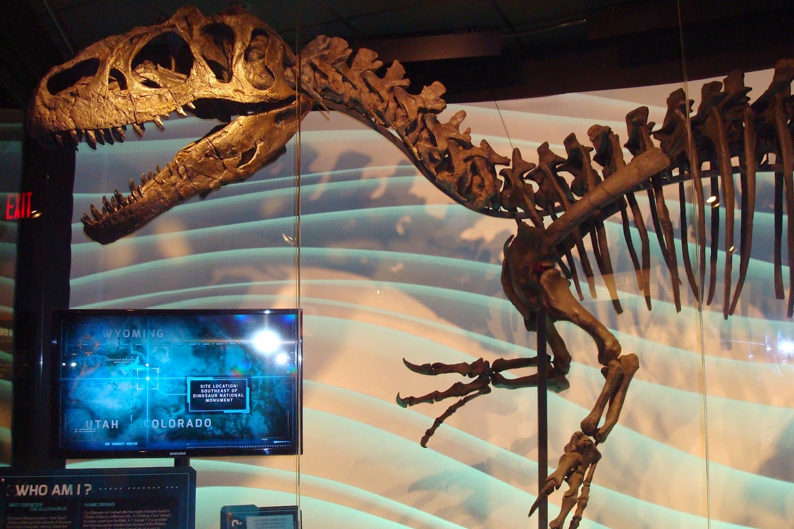
Here is a picture taken from the video of it in demo mode:
After that picture was taken I managed to get it working on its batteries.
Here is the code for the demo.
// Robo-Raptor Demo
// demonstrates several actions the robo raptor can take.
// Written December 2013 by Bob Davis
#include Servo.h
// create servo object to control a servo
Servo myservo;
// mororr moves the right leg
// create motor #2, 64KHz pwm
AF_DCMotor motorr(2, MOTOR12_64KHZ);
// motorl moves the left leg
// create motor #4, 64KHz pwm
AF_DCMotor motorl(4, MOTOR12_64KHZ);
// motorw wiggles the tail, head moves too
// create motor #1, 64KHz pwm
AF_DCMotor motorw(1, MOTOR12_64KHZ);
// motorh moves the head up and down
// create motor #3, 64KHz pwm
AF_DCMotor motorh(3, MOTOR12_64KHZ);
char INBYTE;
// Set A6 as an output pin for speaker
int SpkrPin = 19;
int roar;
void setup() {
motorr.setSpeed(255); // set the speed to 255/255
motorl.setSpeed(255); // set
the speed to 255/255
motorw.setSpeed(255); // set
the speed to 255/255
motorh.setSpeed(255); // set
the speed to 255/255
pinMode(SpkrPin,
OUTPUT);
// The servo is on
pin 9
myservo.attach(9);
}
void loop() {
// Sequence of Motor
control commands:
// wait for tail
switch to get started
// wiggle tail back
and forth
// raise and lower
head three times
// take a few steps
walking forward
// make a roaring
sound
// Wait for tail
switch to start demo
while
(analogRead(A0) != '0'){}
// wiggle tail
motorw.run(BACKWARD); // wiggle
right
delay(200); // pause
motorw.run(RELEASE); //
stopped
delay(300);
motorw.run(FORWARD); // wiggle left
delay(200); // pause
motorw.run(RELEASE); //
stopped
delay(300);
motorw.run(BACKWARD); // wiggle
right
delay(200); // pause
motorw.run(RELEASE); //
stopped
delay(300);
motorw.run(FORWARD); // wiggle
left
delay(200); // pause
motorw.run(RELEASE); //
stopped
delay(300);
motorw.run(BACKWARD); // wiggle
right
delay(200); // pause
motorw.run(RELEASE); //
stopped
delay(300);
motorw.run(FORWARD); // wiggle
left
delay(200); // pause
motorw.run(RELEASE); //
stopped
delay(300);
// raise and lower
head
motorh.run(FORWARD); // raise
head
delay(300); // pause
motorh.run(BACKWARD); // lower
head
delay(300); // pause
motorh.run(RELEASE); //
stopped
delay(500);
motorh.run(FORWARD); // raise
head
delay(300); // pause
motorh.run(BACKWARD); // lower
head
delay(300); // pause
motorh.run(RELEASE); //
stopped
delay(500);
motorh.run(FORWARD); // raise
head
delay(300); // pause
motorh.run(BACKWARD); // lower
head
delay(300); // pause
motorh.run(RELEASE); //
stopped
delay(500);
// walk straight
forward
motorr.run(FORWARD); // right
foot forward
delay(300); // pause
motorr.run(BACKWARD); // right
foot backward
delay(300); // pause
motorr.run(RELEASE); // stop
right foot
delay(300); // pause
motorl.run(FORWARD); // left
foot forward
delay(300); // pause
motorl.run(BACKWARD); // left
foot backward
delay(300); // pause
motorl.run(RELEASE); // stop
left foot
delay(300); // pause
motorr.run(FORWARD); // right foot forward
delay(300); // pause
motorr.run(BACKWARD); // right
foot backward
delay(300); // pause
motorr.run(RELEASE); // stop
right foot
delay(300); // pause
motorl.run(FORWARD); // left
foot forward
delay(300); // pause
motorl.run(BACKWARD); // left
foot backward
delay(300); // pause
motorl.run(RELEASE); // stop
left foot
delay(300); // pause
//open mouth
myservo.write(0);
delay(300);
// roar
for (roar=200; roar
> 0; roar--) {
digitalWrite(SpkrPin, HIGH); //
sets the speaker on
delay(random(10)); // waits
for a fraction of a second
digitalWrite(SpkrPin, LOW); //
sets the speaker off
delay(random(10)); // waits
for a fraction of a second
}
//close mouth
myservo.write(90);
delay(300);
}


.jpg)