Wednesday, October 15, 2014

Building my own 3D printer part 3 and the first video


My 3D printer had its first test run last night.  So far I need to replace the X axis stepper motor it has a bad connection inside of it somewhere as can be seen in this video on Youtube.

http://youtu.be/s77h1BQ-EVQ

Here is a picture of the jumpers to convert the Ramps board to a printer 25 pin interface.  I only connected to the pins that I needed for X, Y, and Z for Step, Direction and Enable, they are blue, green and yellow.  The enables are all connected to ground.  Then I also needed to connect to ground and 5 Volts, they are yellow and red, the top two connections..


Here is another video of the DIY 3D printer this time it is running with and Arduino Mega.

http://youtu.be/YemKKhmJT2o

Here is a picture of the Ramps wiring.  The heat bed is not wired up yet.
Here is the wiring with the heat bed wires in.  I spliced the ribbon cable into some 14 gauge stranded cable and covered the splice with heat shrink.

Here is the third video.  This was my first extrusion attempt.


Here is what I got from my first attempt at making something.  It was supposed to be a 8mm bearing support.


Tuesday, October 7, 2014

Building my own Mendel 90 3D printer part 2

My 3D printer is coming along quite nicely but slowly.  I have started doing the electrical wiring as can be seen in this picture.  Notice the custom made aluminum motor mounts and the use of standard "off-the-shelf" parts throughout.  My next book will give the details of construction it will be titled "Inexpensive 3D Printer Projects".


I purchased standard ends for the X-Axis ends but I have come up with plans as to how to make my own X Axis ends.  I really think even the X Axis ends can be made with standard parts and a piece of Plexiglas or aluminum to hold it together.  The only tricky part would be the "Nut bracket".  That could be made out of Plexiglas.  Just drill a 1/2 inch hole in it and then melt the 5/16" nut into the hole.

Here is a picture of my homemade X axis carriage.  I had to cut the 1/2 inch pipe supports to fit them in the space available (There is approx 2.05 inches between the rails).  The two holes at the back are for mounting the Extruder. The holes at the front already existed but they are for the belt clamps.  The center hole was just a little over 1.25 inches in diameter but it was not big enough to lower the hot end down through.  I had to disassemble it and reassemble it through the hole.  I need to cut off 1/2 inch at the front as it is not needed.  I changed the design and moved the holes out 1/8 an inch.  Then I countersunk them and used flat head 6-32 screws.  Now the print head sits flush.

It is almost done!  Just the 25 pin connector at the bottom right and the heatbed to wire up and it will be done.  Here is what it looks like at this point.


Tuesday, September 23, 2014

Building my own 3D printer based upon Prusa and Mendel90 designs

I have been trying to build my own 3D printer.  I am trying to use "off the shelf" parts as much as possible. I did end up buying X axis ends on eBay.  I designed and made my own stepper motor mounts.

Here is a picture of the frame as I first assembled it.  The blue tape is so I can write on it for my hole markings.

Right now I am stuck on the lead screws for the Z axis.  The holes for the nuts are .55 inches across and they are supposed to be for 8mm nuts.  But 8mm nuts are .51 inches and 5/16 nuts are .5 inches. Both nuts rotate freely in the hole as the hole is for a nut that is .55 inches across.  The nuts that are found on hollow electrical threaded pipe commonly used in table lamps fit perfectly.  One of these is seen on the right side below.  However that would be hard to adapt that to the 5mm stepper motor shafts!


Some of the other problems I have faced so far include:

The stepper motors came with gears on them.  I used a gear puller to remove the gears.  When I connected the motors up to the lead screws I discovered that their shafts were bent so much that the top of the lead screws rotated in about a one inch circle.  I had to get new stepper motors.  When I installed the new stepper motors I discovered that the problem was actually the 5mm to 8mm shaft coupler!  It was drilled so crooked that it causes the lead screw to rotate.

As I said above the holes for the nuts in the X axis ends are .55 inches across and both 8mm and 5/16 nuts spin freely in them.  I might have to make my own "nuts" out of aluminum using a 5/16 tap.   Wow was I really off on that one.  It turns out that the nut holes on the top are .55 inches but the nut holes on the bottom are .51 inches!  So I was just looking at the wrong nut holes.

When I assembled the Y axis carriage and slid it towards the back it returns back to the front on its own!  That is because the rod spacing varies by 1/8 of an inch causing the bearings to bind.  I enlarged the holes on the back side and adjusted it so the platform moves smoothly now.

The 8mm bearings are terrible.  They do not move smoothly and they loose some of their balls every time I remove them from the rods.  I might have to replace them with better ones from another vendor?

Some of the 8mm rods are from printers and scanners.  The one on the right side is a tiny bit bigger than 8mm.  I used emery cloth to take it down a little bit so that the bearings move smoothly.

I used 10mm rods (from scanners) and bearing for the Y axis.  They work so much better than the 8 mm bearings.  However their outside diameter does not fit either 1/2 or 3/4 pipe holders.

The spacing of the z axis guide rods varies by 1/8 of an inch from the top to bottom.  That is a tricky measurement since there are rod holders at the top and a home made motor mount at the bottom.  I will have to move the rod holders in about 1/16 of an inch on each side to fix the problem.

While testing the Y axis I realized that the gantry is at the wrong position.  When I move the Y carriage back the print head will not reach the front edge.  I had to unbolt the gantry and move it forward one inch to resolve the problem.  It was six inches from the back edge but it is now 7 inches from the back edge.

The Y axis bearing holders hits the stepper motor that is mounted under it.  That is because I mounted the stepper motor all the way to the right.  It needs to be moved at least an inch to the left. It also needs to be moved so that the wires to the Y platform can be run in the center, the drive belt is there currently.

I cannot put nuts on the Y axis hot plate screws.  The bearing holders are too close to the front and back edge of the Y platform so there is not enough room to put the nuts on the hot plate screws.  I will have to move the Y axis bearing holders 1/4 inch further from the front and back edges.

I tried to mount the Arduino Mega, but like all Arduino's the mounting holes are an afterthought.  I wanted to have screws come through the plastic, then a nut, an insulator then through the Arduino then a last nut.  However the nuts cannot be on that side.  I am trying to rework it to use the standoff's that are used for ports on a PC.

Tuesday, July 29, 2014

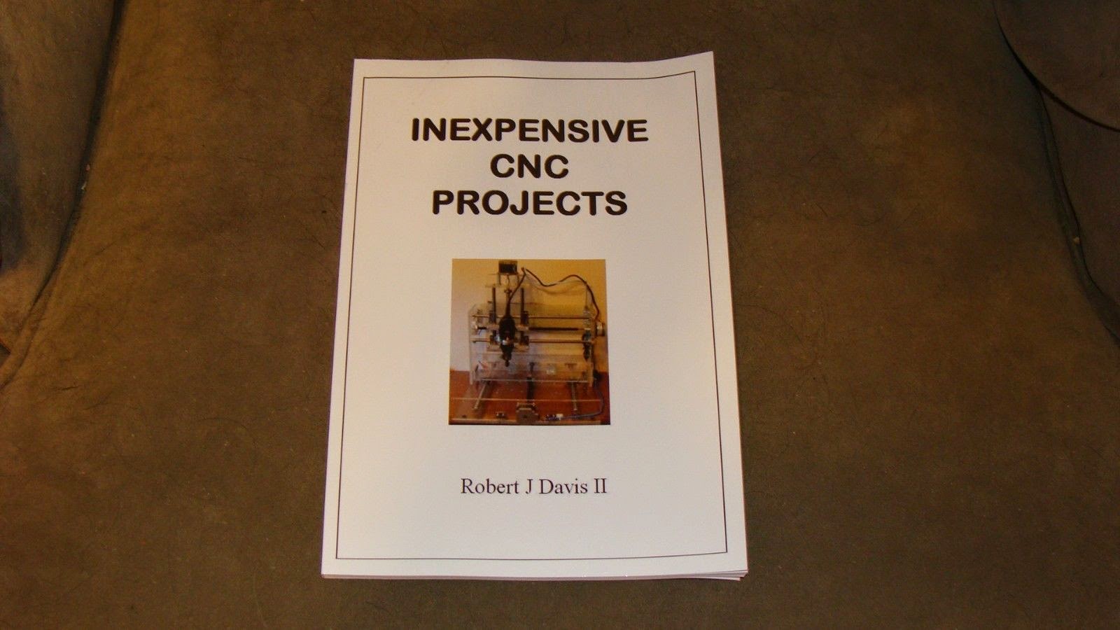
I upgraded my CNC with a router for my book "Inexpensive CNC Projects".

I have added a router to my homemade CNC machine.  It used to smoke at a feed rate over 20% with the Dremel.  Now with the router it can cut at 100% and the cuts are much smoother.

It can also cut right through the board.  I changed the feed rate while the Z axis was moving and caused it to crash, almost cutting through the board.  That is visible in the bottom left side of the "N".
Here is the video, it was taken after the crash.
http://youtu.be/k2YVhZnzZ2k


I am also upgrading it to an aluminum frame, this makes the machine more solid than Plexiglas.

This CNC machine can be built with my plans found in my latest book "inexpensive CNC Projects".

Monday, July 21, 2014

My latest book "Inexpensive CNC Projects" and a trip to Florida

I just returned from a quick trip to Florida.  I drove for over 3,000 miles in only eight days!  I went to visit my dad and to give him a copy of my latest book "Inexpensive CNC Projects".  It is dedicated to him because he was a CNC programmer at Ingersol Rand for many years.

Here is a picture of me giving him the book at the nursing home.

We also stopped at the creation museum on the way home.  I was studying the skeletons of the dinosaurs and how they were animated to get ideas for making my next project - a life sized robo raptor!

Here I am next to an animated raptor.

Here is a picture of a raptor skeleton.

Monday, June 23, 2014

One Crazy Virus claimed to be from the "Metropolitan British Police"

Someone showed me a computer this weekend with a virus that I could not even beat in safe mode.  All I could do was to re-install Windows.  The best I could do was to get the task bar to pop up for a split second.  In safe mode the computer just restarts into regular mode and went back to this screen.
 I had to use a camera to take a picture of it.

Another problem is that Malwayre-Bytes anti Malware (MBAM) no longer offers a thorough search and even once I re-installed windows it did not detect the virus as it was in "Old Windows".  Then there is Microsoft security essentials that will not do a scan unless you are connected to the Internet to do an update.....

Monday, June 16, 2014

2014 Chafee NY Hamfest

The Chaffee NY Hamfest was a little bigger than last year.  It is still one of the smallest ones that I go to.  Here are some pictures that I took.

Here is my table.  It was so cold that I never used that chair.  Note the bin of 5 inch RF cavities.  I was selling it for a friend but did not get any offers.

Note that their were vendors on both sides of the "road".

There was some spare room under th roofs but it was not raining.

Wednesday, May 21, 2014

Element FLX-2211B 22 inch LCD TV Repair

My daughters LCD TV recently died.  She said that it would have to warm up for a while before it would turn on and then finally it did not turn on at all.  I told her that the power supply needed new caps and proceeded to take it to my shop to fix it.

The first problem was how to get it apart.  There is a hidden screw that you have to remove first.  Remove the lower part of the base to get to it.  Then to the left of where the base attaches there is a screw up in there to remove as seen in this picture.  Then the rest of the base comes off.

The power supply only needed two capacitors, they are marked with red arrows, but you can replace a few more capacitors if you want "just in case."

Here is the back cover of the LCD TV for identification purposes.


Friday, May 16, 2014

Homemade DIY CNC Pendant to test out CNC equipment

Last night I finished building my DIY CNC pendant and tested it out.  I still need to add a manual jogger to it someday.  It is made out of an old Zenith TV remote control.  The key is to have three position toggle switches.  I have a lot of them laying around that were left over from another project.  You can build this for about $25 or for free in my case because I used parts that I had laying around.  It will be in my next book "Arduino CNC Projects".

Here is what the insides of the CNC Pendant look like.  The 555 is on the left side and the 9 volt battery is only safe to use if all of your CNC inputs have opti-couplers.  The cable is a 4 pair network cable.

This is the schematic diagram of the wiring of the direction switches.  You need either 6 Volts or you can use 9 volts and a 5 volt regulator.

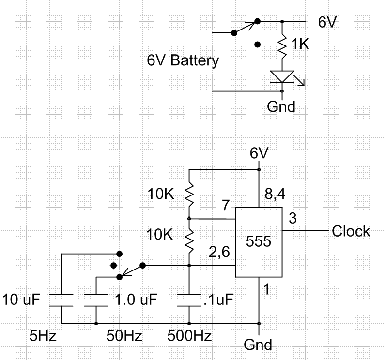
This is the wiring of the 555 timer and the power switch.  Either use 6 volts or add a 5 volt regulator to protect your BOB (Break out Board) from the excessive voltages.  I was using an old battery that was only putting out about 6 volts.  You might also be able to tap into 5 volts from your CNC.
Here is a link to a video of the homemade CNC and this pendant working.  This video was from before the 555 was put inside of the pendant.  http://youtu.be/nbSun9bJMPo

Here is what the DIY CNC looks like today.
Here is the latest video on YouTube: http://youtu.be/YB4Aem0amOo

Wednesday, April 30, 2014

DIY Raised Gardens in NY with very little land

Last year I started a small raised garden.  I started the plants indoors in March and then moved them outdoors into two raised beds made out of 2 by 6's.  Each one was about 8 feet by 3 feet in size.

Last year I used egg cartons to start the plants, they were way too small!  This year I used mostly yogurt containers to start my plants.  The plants seem to thrive in these yogurt containers.  I poked a hole in the bottom of them to help prevent over-watering.  I also bought some plant starter kits.  They were a total flop, only about 8 out of 36 plants grew!  All of the seeds in the yogurt containers grew.  The problem with the starter trays is that the "dirt" must be pointed up before the water is added. Otherwise the dirt expands crosswise and is under too much pressure for the plants to grow.  Also the potting soil that was used in the yogurt containers is far more effective in starting plants.

Here is a picture of them after about a month.  The cardboard type of seed starters are better than the yogurt containers in the long run.  They are ready to go in the ground, half of them are already planted.

Here is what my garden looked like last year when everything was first planted outside.  The peas are in the front row.

This is an update - the garden in June.

This is what the garden looked like at the end of last summer.  The peas have died and cucumber and zucchini have taken over.
Another secret to gardening is to use rain water.  I have a large plastic trash can that fills with rain water to keep the garden watered.  If you must use tap water then let it sit overnight first.

Tuesday, April 15, 2014

DIY Arduino CNC Projects for 3D printing, engraving, etc.

I am working on making my own Arduino powered CNC 3D printer and light duty milling machine.  It started off as just some pieces of Plexiglas and parts salvaged from some old scanners and printers.  I will likely write my next book about building your own "Arduino CNC Projects".
I added some wood for the main platform and used an old LED sign board to hold the electronics.  The Robo raptor is jealous that I am no longer playing with him.
I bought a ball screw drive for the Z axis on eBay and figured out how to mount it.  The X and Y axis were belt driven but kept binding up and had too much play in them.
Next I upgraded to NEMA 23 stepper motors and ball screw drives for the X and Y axis.  Now it runs much smoother.
The mechanical part is just about done, but the electronics will need a lot of work before it starts running. Currently the Arduino is driving the steppers through some L298 driver IC's.

Here is the electrical so far.  I have built a L297 interface board but it is still not working properly.

Here is a link to the video on youtube: https://www.youtube.com/watch?v=RL-55GaYAvs

Wednesday, April 9, 2014

Projectors for Africa Part 2

Years ago I was in Africa with my brother.  We were setting up a video Bible school and we purchased a large TV to show the video's on.  However the guy using the TV only had a bicycle to haul it around with.  I thought "If only I could send over some Projectors!"  That year we started sending video projectors to Africa.

Last year I refurbished over 20 Video projectors for use in Africa and in the Philippines.  This year I have already purchased over a dozen used projectors that need to be refurbished.  That included cleaning and adding a new air filter.

My brother just took a load of projectors over to Africa and sent back these pictures of happy pastors.  He includes a Video Bible School and some of his teaching Video's.


We need DVD players, power cables, VGA cables and A/V cables.  If you have any you want to donate let me know.

RAWNY Mini Hamfest in Tonawanda NY

Last night I attended the RAWNY mini Hamfest in Tonawanda NY.  It was actually fairly well attended and I got rid of at least 3 boxes of stuff as well as sold about 5 or 6 books.
Here is a picture showing the awarding of the prizes.
Here is my table.  Someone said that i had the cleanest table there.  I had all my free junk hidden underneath it!
I might have brought home almost as much stuff as I took.  I collected several 12 volt 5 amp AC adapters for free.  I purchased many VGA cables for $3 each.  I even picked up something that I did not know what it was.  I think it might be a serial port RS-232 to Coax converter.

Friday, January 31, 2014

Arduino powered Roomba Robot

I have taken a iRobot Roomba vacuum cleaner apart and made an Arduino Powered robot out of it.  There is a serial port on the Roomba, but mine was dead so I wanted to do a complete rebuild.  I am using a L298 motor controller IC.  The Arduino is on the back right corner in the picture below.

At first I was just interested in how much power the Roomba has.  It easily got around with about 20 pounds of added weight and could push chairs out of its way.  My long term goal is to make a life sized robo-raptor and this would make a nice foot.  I have videos of a 2 foot long robo-raptor also under control of an Arduino.

Here are the videos:
http://www.youtube.com/watch?v=6Kd9IM1UDb8

http://www.youtube.com/watch?v=f9-WJ3wGICo

Thursday, January 9, 2014

Arduino powered Robo-Raptor

I have been working on rebuilding a Robo Raptor to be controlled by an Arduino.  It is a key project in my latest book "Arduino Robotics Projects" available on Amazon.

Here is a link to the video on YouTube:
http://youtu.be/O8E3QBfjXO0

Here is a picture of the Arduino and motor control shield attached to the robo raptor:

Here is a picture taken from the video of it in demo mode:
After that picture was taken I managed to get it working on its batteries.

Here is the code for the demo.

// Robo-Raptor Demo
// demonstrates several actions the robo raptor can take.
// Written December 2013 by Bob Davis

#include AFMotor.h
#include Servo.h
// create servo object to control a servo 
Servo myservo;
// mororr moves the right leg
// create motor #2, 64KHz pwm
AF_DCMotor motorr(2, MOTOR12_64KHZ);
// motorl moves the left leg
// create motor #4, 64KHz pwm
AF_DCMotor motorl(4, MOTOR12_64KHZ);
// motorw wiggles the tail, head moves too
// create motor #1, 64KHz pwm
AF_DCMotor motorw(1, MOTOR12_64KHZ);
// motorh moves the head up and down
// create motor #3, 64KHz pwm
AF_DCMotor motorh(3, MOTOR12_64KHZ);
char INBYTE;
// Set A6 as an output pin for speaker
int SpkrPin = 19;
int roar;

void setup() {
  motorr.setSpeed(255);     // set the speed to 255/255
  motorl.setSpeed(255);     // set the speed to 255/255
  motorw.setSpeed(255);     // set the speed to 255/255
  motorh.setSpeed(255);     // set the speed to 255/255
  pinMode(SpkrPin, OUTPUT);
  // The servo is on pin 9 
  myservo.attach(9); 
}

void loop() {
  // Sequence of Motor control commands:
  // wait for tail switch to get started
  // wiggle tail back and forth
  // raise and lower head three times
  // take a few steps walking forward
  // make a roaring sound 

  // Wait for tail switch to start demo
  while (analogRead(A0) != '0'){}

  // wiggle tail
  motorw.run(BACKWARD);    // wiggle right
  delay(200);  // pause
  motorw.run(RELEASE);     // stopped
  delay(300);
  motorw.run(FORWARD);     // wiggle left
  delay(200);  // pause
  motorw.run(RELEASE);     // stopped
  delay(300);
  motorw.run(BACKWARD);    // wiggle right
  delay(200);  // pause
  motorw.run(RELEASE);     // stopped
  delay(300);
  motorw.run(FORWARD);     // wiggle left
  delay(200);  // pause
  motorw.run(RELEASE);     // stopped
  delay(300);
  motorw.run(BACKWARD);    // wiggle right
  delay(200);  // pause
  motorw.run(RELEASE);     // stopped
  delay(300);
  motorw.run(FORWARD);     // wiggle left
  delay(200);  // pause
  motorw.run(RELEASE);     // stopped
  delay(300);

  // raise and lower head
  motorh.run(FORWARD);     // raise head
  delay(300);  // pause
  motorh.run(BACKWARD);    // lower head
  delay(300);  // pause
  motorh.run(RELEASE);     // stopped
  delay(500);
  motorh.run(FORWARD);     // raise head
  delay(300);  // pause
  motorh.run(BACKWARD);    // lower head
  delay(300);  // pause
  motorh.run(RELEASE);     // stopped
  delay(500);
  motorh.run(FORWARD);     // raise head
  delay(300);  // pause
  motorh.run(BACKWARD);    // lower head
  delay(300);  // pause
  motorh.run(RELEASE);     // stopped
  delay(500);
   
  // walk straight forward
  motorr.run(FORWARD);     // right foot forward
  delay(300);  // pause
  motorr.run(BACKWARD);    // right foot backward
  delay(300);  // pause
  motorr.run(RELEASE);     // stop right foot
  delay(300);  // pause
  motorl.run(FORWARD);     // left foot forward
  delay(300);  // pause
  motorl.run(BACKWARD);    // left foot backward
  delay(300);  // pause
  motorl.run(RELEASE);     // stop left foot
  delay(300);  // pause

  //open mouth
  myservo.write(0); 
  delay(300);

  // roar
  for (roar=200; roar > 0; roar--) {
    digitalWrite(SpkrPin, HIGH);   // sets the speaker on
    delay(random(10));        // waits for a fraction of a second
    digitalWrite(SpkrPin, LOW);    // sets the speaker off
    delay(random(10));        // waits for a fraction of a second
  }
  //close mouth
  myservo.write(90); 
  delay(300);


}


Toshiba L645 Disassembly and fan cleaning.


I recently had a Toshiba L645 come in for a power jack replacement and a fan cleaning.  The power jack comes as a cable assembly that has to be ordered to fit the laptop.  There are some tricks to getting it apart.  There are screws in the battery compartment holding the trim that covers the screws that holds in the keyboard.  There is a screw inside of the memory compartment that holds the CD ROM drive in, and once it is removed there is a screw located above where the drive was.

1 – Remove the 12 bottom screws.
2 – Remove the 2 screws for the hard drive drawer, and remove hard drive.
3 – Remove the battery and remove 5 screws located below the battery.
            The two smaller screws hold the keyboard bezel cover in place.
4 – Remove three keyboard bezel, the screws above the keyboard, and the keyboard.
5 – Remove the seven screws under the keyboard, the right two are shorter.
6 – Remove the 3 screws and the memory cover, inside there is the CD ROM screw.
7 – Remove the CD-ROM drive and the screw hidden above it.
8 – Unscrew and/or unplug the wireless network card.
9 – Unplug the mouse, speakers and power switch, remove the top cover of the laptop.
10 – Un-tape and unplug the video cable, and the USB/VGA jack cable.
11 – Remove three motherboard screws marked with white arrows, and one fan screw.
12 – Remove motherboard with the fan assembly.
13 – Remove 4 super tiny screws and remove the fan cover to clean the fan.

As you can see in the picture the fan was fairly clogged with dust.  A small paint brush can remove the dust.  The picture quality is not that great, I was using my cell phone camera.

When I reassembled it the screen did not work.  The screen plug looked like it was plugged in but it was not inserted properly.  You might want to mark the tape that holds it in with a marker prior to unplugging it so you know if you have it back together correctly.

This picture shows the 5 screws that are located below the battery.  Two of them hold the cover that gives access to the keyboard screws.