Thursday, May 14, 2015

8x8x8 Color RGB LED Cube Project

I am finishing up the biggest project for my latest book on LED cubes.  Here are a couple of video's about the 8x8x8 color LED cube.

In this first video it was just 7x7x2 in size:


In this next video it is up to 7x7x4 in size and still growing as more LED's arrive:


It has now grown to 8x8x4 in size.

I will have to use a pad per hole soldered breadboard to proceed any further.  The 7x7x4 setup takes over 200 jumpers to connect everything.  I would buy a printed circuit board but as far as I know no one makes one that meets my standards!  The closest design I have found uses latches and lots of transistors and resistors.  My design uses nothing but 74HC595 shift registers and a ULN2803.

Here are the red, green, blue and white test pictures.


And now the schematic for one layer...
Someone pointed out that the resistor values are not given in the schematic above.  You can use from 47 to 100 ohms, I was using 51 ohm resistors.

Tuesday, May 12, 2015

TDA-03211C 32 inch LCD Monitor Repair

I was at a yard sale and I asked them about a 32 inch TV.  They said it was free because the screen did not light up.  It turned out to be the same model and have the same problem that I have diagnosed before.  It was bad capacitors in the HV power supply for the backlight.

Here is a picture of the bad 10 uF at 450 volt capacitors.

I replace them with 2 or 4 uF at 400 volt paper capacitors.  There is a hole pattern already there for the larger capacitors.  This picture shows the old holes and the new holes to use.

Here is what the new capacitors look like installed on the High Voltage power supply.

Friday, May 1, 2015

8x8x8 LED cube kit completed

I completed the third application for my 8x8x8 LED cube.  First it was to use it with an Arduino, then with a Raspberry Pi and then this kit that I bought on eBay.  At first I thought it was not working because it is so dim that you have to turn down the lights to watch it.  Once that problem was fixed I then reverse engineered it to work with an Arduino once again.

Here is the front view of the completed 8x8x8 LED cube kit.

 This is the back view.  You can see the wires going up to the eight layers.

Here is the bottom view so you can see the IC's.

This it the video of it on YouTube.

The design problem is that there should be a resistor in each LED leg, that would take 64 resistors.  Instead they used 8 resistors in the common cathode circuit.  As a result the brightness of each layer varies depending upon how many LED's are lit up.  The more led's are lit the dimmer the layer becomes.  I might try to fix this by adding a resistor on each of the 64 legs and removing the ones on the common cathode connection to each layer.  If nothing else reducing the 500 ohm resistor to 100 or 220 ohms might do the trick.

Here is the quick fix - just change the 510 ohm resistors to 51 ohms.  Then the display is much brighter.  It is still not as bright as when I used 74595 shift registers.
I am now reverse engineering this LED cube to allow an Arduino to control it.
Here is the completed modification.  It requires adding a 74LS138 IC.  The latches need to be changed to 74HC574's to make it work properly with an Arduino.
This is the schematic diagram.

Here is a video of the cube kit working with the Arduino Uno.

Once it was interfaced to the Arduino I used a spare analog pin to add sound to it.

This is the schematic of the resulting cube:


Tuesday, April 28, 2015

I am working on a book of LED Cube Projects

I have been working on a book of LED Cube Projects.  It might end up being two books one for the Arduino and one for the Raspberry Pi.  So far I have built a 4x4x5 LED cube and a 8x8x8 LED cube. Coming up next is a Color Cube likely 6x6x6 in size.

Here is a picture of the 8x8x8 LED Cube from above.


This first picture is of a 3D slice cutting through the cube.


Here is a link to the video: https://youtu.be/g9kaYzO85oM

This next video is of "falling rain" 


Here is a link to that video: https://youtu.be/-tZJ-3NSlhY

Here is a picture of it running with a Raspberry Pi.
Here is a link to that video: https://youtu.be/eRgVuaLHWls

Thursday, April 23, 2015

Epson Powerlite 62C Repair

I recently purchased another pile of used projectors to repair and then send to Africa.  However three of them need more than just cleaning.  I have determined that the problem is in the optics.  Basically the blue LCD is about 30-50% shot.  There are lots of dark spots in a blue background.
The problem is that the LCD section is one unit otherwise I could swap the LCD's between the three projectors and hopefully get two of them to work.

I like the Epson LCD projectors because they are a lot more rugged that the Dell 2300MP DLP projectors.  However the LCD's have an air filter and if it gets clogged the projector overheats and damages the LCD's.  I explained how to replace the filter in a previous post.

Here is what the outside of them looks like.

Wednesday, April 15, 2015

RAWNY Mini Hamfest Buffalo NY

Once again this year I attended the mini Hamfest.  It is just for a couple hours in the evening but you get to talk to a lot of interesting people as well as sell and buy a lot of stuff.  I think I managed to leave with less stuff than what I came in with.

Here is a picture of my table.  I did not bring the bins from my shed this year.

Here is another table or two.

Here was some really nice radio's.  Sorry I chopped off the picture of the seller....

And here are some more tables of great stuff!


Thursday, April 9, 2015

Refurbishing Projectors for Africa.

I spent a weekend fixing seven Dell 2300MP Projectors.  In every projector the power supply was not working.  I replaced the same capacitor in all seven projectors.  The problem part is a 22uF at 50 volt cap.  I replaced it with a 22uF at 63 volt cap.  Out of the seven projectors changing the capacitor fixed five of them.  One power supply had some burnt parts and a burnt circuit board.

This is what my closet looks like.  The 2300MP projector are on the right.

Here is a picture of how to bend the leads on the capacitor.

This picture shows where the capacitor goes.  It is not yet soldered in the picture.

 Here is a picture of a pile of projectors, I worked on them three or four at a time.

I had to glue some of the power supply support posts in place.  The projectors had all been dropped, likely in shipping, and the support posts that hold them together were loose.

Wednesday, March 18, 2015

Raspberry Pi and a DIY 4x4x4 LED cube

I have built a DIY 4x4x4 LED cube that I am testing with the Raspberry Pi.  It is up and working, I just need some code to make it do something that is "moving".  Pun intended.  It is only doing fixed patterns at this point.

Note that my design is quite different.  For one thing all 4 LED frames are easily removed for servicing.  So far I have had one bad LED and a soldering connection that needed fixing.  I also need to replace one LED that has a slightly different color.  It is the third one up from the bottom in the center.

My 4x4x4 LED cube is also designed to be expanded to 4x4x5 or 6 as adding them will not require any more IC's.  Also when you order LED's they come in bags of 100 so why not use all of them? There are currently two 74HC595's and a ULN2003 driving it.

I drilled a wood guide and rebuilt the arrays so they are right to left instead of front to back.  I also added the fifth row while I was at it.  I broke a couple of LED's in the process but it is up and running again.


Here is a picture of the LED test program running to make sure everything works.  I need to replace a bad LED and find a way to keep the LED arrays parallel to each other.  I might give in and add some wire braces across the top corners.  The braces could be un-soldered to work on the arrays if needed.


Here is the video on Youtube.


Friday, February 27, 2015

Running a 8x40 LED Array from the Raspberry Pi

I have been trying to run one of the 8x40 LED signs from a Raspberry Pi.  For some reason I am getting a lot of glitches.  I know the Raspberry Pi can cause glitches when the GUI is running, but this is different.  UPDATE - I fixed the glitch it was a bad ground on the ribbon cable.

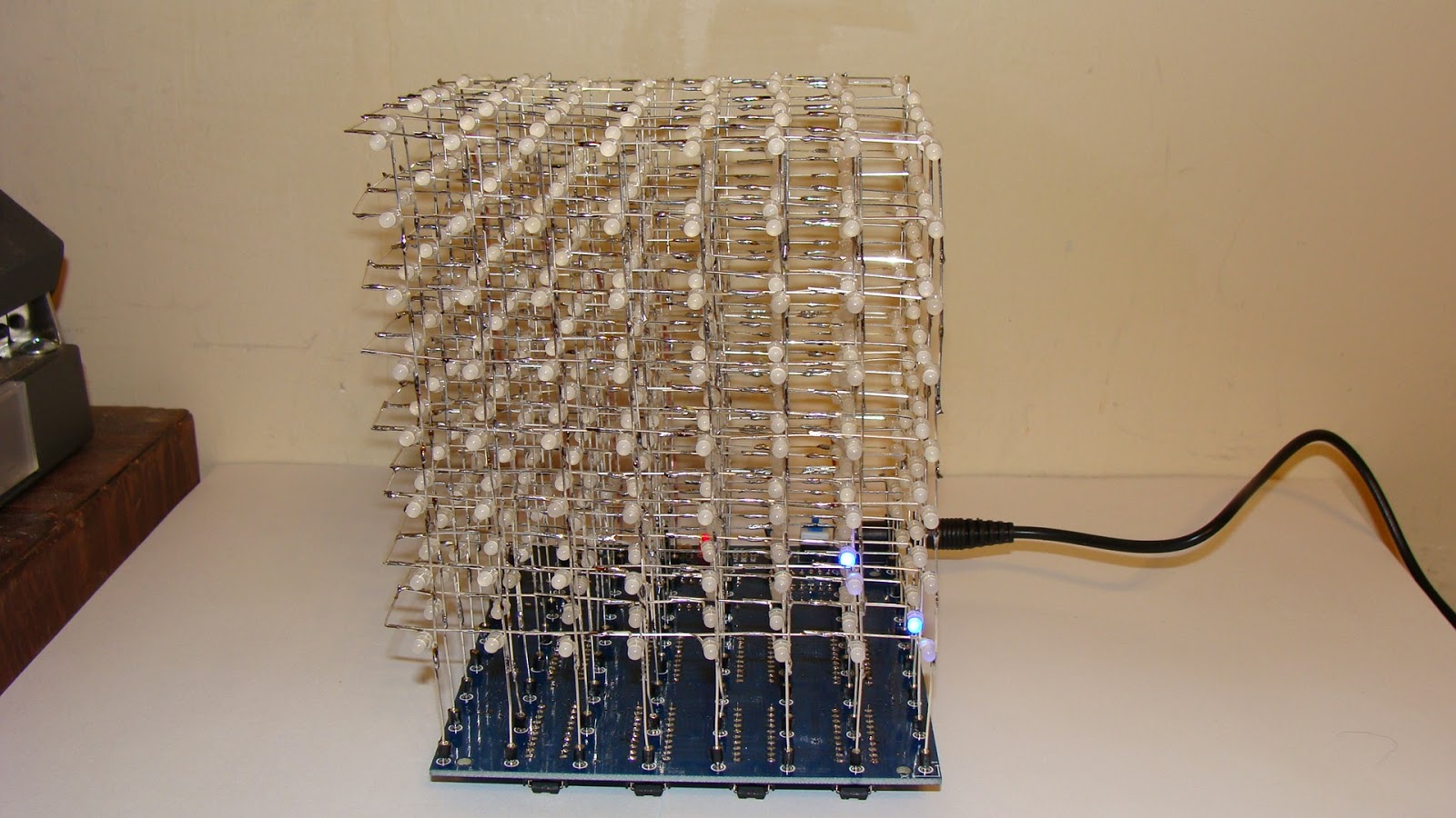
This is what it looks like.  A glitch is happening over the letter "Y".
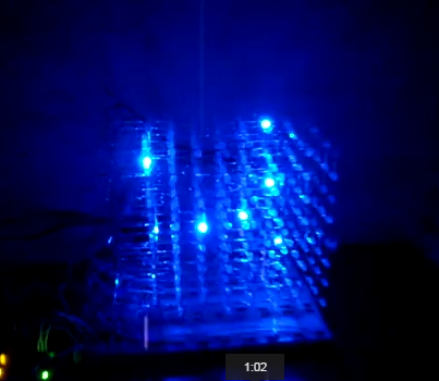
Here is a video showing the glitching.
https://www.youtube.com/watch?v=n4tE-9H_Adg&feature=youtu.be

Another problem is that I cannot figure out how to do what is called macro substitution in python.  As a result the code is a bit long.  If I could say "if red&row[shift]=1" I could eliminate several lines of code. UPDATE - I have a solution.  Make the letter arrays into one big array for each letter.  Then use "if red[shift+row*5]".  I have used that technique for working with some other devices.

Here is my code to make it work:
# LED 8x40 Dual Color array
# Uses individual letters strung together
import RPi.GPIO as GPIO
import time
GPIO.setmode(GPIO.BCM)

GPIO.setup(17, GPIO.OUT) # Red Data
GPIO.setup(18, GPIO.OUT) # Green Data
GPIO.setup(27, GPIO.OUT) # Clock, 21 on older
GPIO.setup(22, GPIO.OUT) # Latch
GPIO.setup(23, GPIO.OUT) # Row Data 1
GPIO.setup(24, GPIO.OUT) # Row Data 2
GPIO.setup(25, GPIO.OUT) # Row Data 4
GPIO.setup(4, GPIO.OUT) # Row Enable

A1 =[0,0,0,0,0]
A2 =[0,0,1,0,0]
A3 =[0,1,0,1,0]
A4 =[1,0,0,0,1]
A5 =[1,1,1,1,1]
A6 =[1,0,0,0,1]
A7 =[1,0,0,0,1]
A8 =[1,0,0,0,1]

B1 =[0,0,0,0,0]
B2 =[1,1,1,1,0]
B3 =[1,0,0,0,1]
B4 =[1,0,0,0,1]
B5 =[1,1,1,1,0]
B6 =[1,0,0,0,1]
B7 =[1,0,0,0,1]
B8 =[1,1,1,1,0]

E1 =[0,0,0,0,0]
E2 =[1,1,1,1,1]
E3 =[1,0,0,0,0]
E4 =[1,0,0,0,0]
E5 =[1,1,1,1,0]
E6 =[1,0,0,0,0]
E7 =[1,0,0,0,0]
E8 =[1,1,1,1,1]

P1 =[0,0,0,0,0]
P2 =[1,1,1,1,0]
P3 =[1,0,0,0,1]
P4 =[1,0,0,0,1]
P5 =[1,1,1,1,0]
P6 =[1,0,0,0,0]
P7 =[1,0,0,0,0]
P8 =[1,0,0,0,0]

R1 =[0,0,0,0,0]
R2 =[1,1,1,1,0]
R3 =[1,0,0,0,1]
R4 =[1,0,0,0,1]
R5 =[1,1,1,1,0]
R6 =[1,0,0,0,1]
R7 =[1,0,0,0,1]
R8 =[1,0,0,0,1]

S1 =[0,0,0,0,0]
S2 =[0,1,1,1,1]
S3 =[1,0,0,0,0]
S4 =[1,0,0,0,0]
S5 =[0,1,1,1,0]
S6 =[0,0,0,0,1]
S7 =[0,0,0,0,1]
S8 =[1,1,1,1,0]

Y1 =[0,0,0,0,0]
Y2 =[1,0,0,0,1]
Y3 =[1,0,0,0,1]
Y4 =[0,1,0,1,0]
Y5 =[0,0,1,0,0]
Y6 =[0,0,1,0,0]
Y7 =[0,0,1,0,0]
Y8 =[0,0,1,0,0]

# Z is used as a blank
Z1 =[0,0,0,0,0]
Z2 =[0,0,0,0,0]
Z3 =[0,0,0,0,0]
Z4 =[0,0,0,0,0]
Z5 =[0,0,0,0,0]
Z6 =[0,0,0,0,0]
Z7 =[0,0,0,0,0]
Z8 =[0,0,0,0,0]

Red1=R1+Z1+S1+P1+Z1+E1+R1+Z1
Red2=R2+Z2+S2+P2+Z2+E2+R2+Z2
Red3=R3+Z3+S3+P3+Z3+E3+R3+Z3
Red4=R4+Z4+S4+P4+Z4+E4+R4+Z4
Red5=R5+Z5+S5+P5+Z5+E5+R5+Z5
Red6=R6+Z6+S6+P6+Z6+E6+R6+Z6
Red7=R7+Z7+S7+P7+Z7+E7+R7+Z7
Red8=R8+Z8+S8+P8+Z8+E8+R8+Z8

Green1=R1+A1+Z1+P1+B1+Z1+R1+Y1
Green2=R2+A2+Z2+P2+B2+Z2+R2+Y2
Green3=R3+A3+Z3+P3+B3+Z3+R3+Y3
Green4=R4+A4+Z4+P4+B4+Z4+R4+Y4
Green5=R5+A5+Z5+P5+B5+Z5+R5+Y5
Green6=R6+A6+Z6+P6+B6+Z6+R6+Y6
Green7=R7+A7+Z7+P7+B7+Z7+R7+Y7
Green8=R8+A8+Z8+P8+B8+Z8+R8+Y8

# set up the loop
cycle= 0
while cycle < 1000:
  row = 0
  while row <9: 

    row = row+1
    # Send data to the shift registers
    shift = 39
    while shift >= 0:
        GPIO.output(17, GPIO.LOW)
        GPIO.output(18, GPIO.LOW)
        # determine if bit is set or clear data is NOT inverted
        if row==1:
          if Red1[shift] == 1: GPIO.output(17, GPIO.HIGH)
          if Green1[shift] == 1: GPIO.output(18, GPIO.HIGH)
        if row==2:
          if Red2[shift] == 1: GPIO.output(17, GPIO.HIGH)
          if Green2[shift] == 1: GPIO.output(18, GPIO.HIGH)
        if row==3:
          if Red3[shift] == 1: GPIO.output(17, GPIO.HIGH)
          if Green3[shift] == 1: GPIO.output(18, GPIO.HIGH)
        if row==4:
          if Red4[shift] == 1: GPIO.output(17, GPIO.HIGH)
          if Green4[shift] == 1: GPIO.output(18, GPIO.HIGH)
        if row==5:
          if Red5[shift] == 1: GPIO.output(17, GPIO.HIGH)
          if Green5[shift] == 1: GPIO.output(18, GPIO.HIGH)
        if row==6:
          if Red6[shift] == 1: GPIO.output(17, GPIO.HIGH)
          if Green6[shift] == 1: GPIO.output(18, GPIO.HIGH)
        if row==7:
          if Red7[shift] == 1: GPIO.output(17, GPIO.HIGH)
          if Green7[shift] == 1: GPIO.output(18, GPIO.HIGH)
        if row==8:
          if Red8[shift] == 1: GPIO.output(17, GPIO.HIGH)
          if Green8[shift] == 1: GPIO.output(18, GPIO.HIGH)
        # advance the clock
        GPIO.output(27, GPIO.HIGH); GPIO.output(27, GPIO.LOW)
        shift=shift-1
    # select the row data is inverted
    GPIO.output(4, GPIO.HIGH) # Turn off display
    if row==2: GPIO.output(23, GPIO.LOW); GPIO.output(24, GPIO.HIGH); GPIO.output(25, GPIO.HIGH)
    if row==3: GPIO.output(23, GPIO.HIGH); GPIO.output(24, GPIO.LOW); GPIO.output(25, GPIO.HIGH)
    if row==4: GPIO.output(23, GPIO.LOW); GPIO.output(24, GPIO.LOW); GPIO.output(25, GPIO.HIGH)
    if row==5: GPIO.output(23, GPIO.HIGH); GPIO.output(24, GPIO.HIGH); GPIO.output(25, GPIO.LOW)
    if row==6: GPIO.output(23, GPIO.LOW); GPIO.output(24, GPIO.HIGH); GPIO.output(25, GPIO.LOW)
    if row==7: GPIO.output(23, GPIO.HIGH); GPIO.output(24, GPIO.LOW); GPIO.output(25, GPIO.LOW)
    if row==8: GPIO.output(23, GPIO.LOW); GPIO.output(24, GPIO.LOW); GPIO.output(25, GPIO.LOW)
    # latch and display the data
    GPIO.output(22, GPIO.LOW); GPIO.output(22, GPIO.HIGH)
    GPIO.output(4, GPIO.LOW) # Turn back on
    # time.sleep(.0005)
  cycle=cycle+1 


Wednesday, February 25, 2015

Raspberry Pi Projects - 8x8 RGB LED array

I have been working on a book of Raspberry Pi projects.  One of the projects is an 8x8 three color LED array.  I picked up some more of them on eBay lately and they had a different pin-out.

The MEU 8860 RGB pin-out as seen from above.  I use Dx for the rows as Rx is used for Red.

R1  R2  G2  R3  G3  R4  D2  D1  D3  G5  R6  G6  D5  R7  B8  R8
                                                                                                     

G1  B1  D7  B2  B3  D8  B4  G4  B5  R5  D4  B6  D6  B7  G7  G8

The bottom row is where the model number is stamped.

Here is a picture of one of the displays wired up and working.


Here is a video of another three color 8x8 LED array in operation.

https://www.youtube.com/watch?v=Wj9w4rqbikk

Here is a video of an 8x15 dual color LED array in operation.

https://www.youtube.com/watch?v=oxbNxy2toeU

Thursday, February 19, 2015

Dell 2300MP DLP Projector Repair

My church had a fairly new Dell 2300 MP DLP Projector that had died.  I came across a video on YouTube that said this one capacitor in the power supply was the problem.  Here is a picture of the old 22uF capacitor to the left of the trensformer.

The new capacitor is a bit tricky to install.  There are surface mount components close to it on the bottom side.  I decided to replace the capacitor on the top side of the circuit board.

Here is a picture of the projector now that it is working.  Just a little more assembly to do.

Tuesday, February 10, 2015

NEC LT-265 LCD Projector repair

The other day I had a NEC LT-265 projector that would not focus and had a rattling sound.  To open it up remove the screws on the bottom, one screw is under the handle and the top cover lifts off at the front first then the back so that that it clears the jacks on the rear.


Removing the lens assembly was not easy.  I had to remove the circuit board first.  There were a lot of screws hidden way down inside and behind things.  When I got to the rattle it was the leveling foot that had gone up inside of the projector.  The focus issue was still there and there was nothing obvious that was causing it.  I took a hold of the lens and forced it to turn and to pull out.  The lens then popped into place and started working!  I guess I never needed to take it apart in the first place.

Thursday, February 5, 2015

Hitachi CP-X809 High power LCD Projector repair.

Yesterday I dissembled a Hitachi CP-X809 Projector to see why "dust" was stuck in between the lenses or LCD's.

There are a lot of screws to remove to get to the LCD assembly.  There are about 6 screws accessed from the bottom of the projector.  You have to remove the cover around the lens first.  There are four screws, two are hidden under a flip out panel that hold the lens cover in place.  There are three screws on the back panel that are not marked.  Then you can remove the top cover.  To remove the circuit boards there are another 6 or 8 screws.  Do not forget the screws on the back cover.


The circuit boards can be folded up and out of the way like this.

You need to disconnect some wires and the three LCD ribbon cables and then the circuit board flips back revealing the LCD and lens assembly.  The plastic around the rear jacks needs to be bent out of the way a little.  Here is the LCD and lens assembly.


Here is the problem with the projector, the left color filter is totally shot.  It was not dust that was causing the problem.  I have never seen one so badly damaged.  It must have been severely overheated.  Does anyone know where to get one of these?


By the way I should point out that this kind of damage is usually from overheating because the air filter is clogged.  Usually it is not this severe.

Tuesday, December 23, 2014

DIY 3D Printer - Printing Small Parts

Here is a picture of a printed 3D hand.  When I first tried to print it I had fingers flying all over the place.  I even tried gluing them down to no avail!

Here is what you can do to make printing small parts possible.
1. Clean the glass with a razor blade.
2. Treat the glass with acetone and/or hair spray.
3. Print a 3mm "Brim" around the base of objects.
4. Print the center or "infill" first, then the edges.
5. Use a soldering iron if needed to remove "bumps".
6. Slow down the acceleration to 1000 or 2000.

Here is a video of the results.
http://youtu.be/6_5nY8F2hQg?list=UU49j5FVUO2KIFyH2IXmGXjg

The problem is that the plastic expands in the Z axis as it cools.  Then when the print head goes over it the part is impacted and sent flying.  If the "infill" is printed first then the edge does not need to be passed over to print the infill.

Wednesday, December 10, 2014

EcoQuest Fresh Air II air purifier repair

I have purchased some junk EcoQuest Fresh Air air purifiers to repair.  I fixed one by replacing the capacitors in the power supply.  I like these air purifiers because they feature an Ozone maker, and Ionizer a UV light (to kill germs) and a normal air filter too!

I have two of these air purifiers that I cannot fix.  They come in two versions.  Version one has a 12 volt switching power supply in the lower left corner.  Then there are three Triacs in the middle that turn power on to the devices.  Then there is a 5 volt regulator over on the right side that powers the logic circuits.  On mine the IC for the 12 volt power supply blew up.  I tried taking a 12 volt AC adapter and powering it up that way.  The green LED comes on indicating that the 5 volt power supply is working.  However the LCD powers up but remains blank.

I labeled the parts in this picture.


My other air purifier is a version two device.  It uses a telephone cord or a SATA cable to connect the LCD Display.  The power supply in the front left corner only puts out about 2 volts and gets very hot. In this model the switching power supply makes 8 VDC, 12 VDC and 40 VDC.  The test points for these are located just above the power supply transformer that is covered in metal in the picture below.

This is a close up showing the power supply test points.

Once again I used an AC adapter to provide 12 volts and 8 volts but it would not power up even then.  However the AC adapter was not loaded down indicating that the switching power supply is at fault.

Does anyone have schematics or anything that would help me in fixing these?

Here is the Viper53 schematic thanks to a commentator:

Here is a link to the documents:
https://ecoquestfreshair.com/upload/iblock/9cf/FreshAir_DofC_10-08-04.pdf

Monday, November 24, 2014

MY DIY 3D Printer update

Here are a couple of tricks I have learned.  When I first started printing everything worked fine.  Then after making about 5 things they started coming loose.  To clean the glass use nail polish remover (Acetone) on a Kleenex.  Then apply 2 or 3 squirts of hairspray.  You may need to spread it around a little.  That surface preparation results in the best adherence of the printed parts.

I have made several upgrades to my 3D printer.  Like for instance an oversize fiberglass Y axis carriage.


Here it is printing out a Mendel90 X axis motor end.  I am working on printing out all the parts of the Mendel90 3D printer.


I used some packaging strap to hold the ribbon cable up.

This is a picture of my new extruder's hot end.  I need to mount the fan to something but it has survived hanging from the wires for quite a while.  Here is a link to a video showing it in operation. http://youtu.be/MVh2b1nGNW8?list=UU49j5FVUO2KIFyH2IXmGXjg

Here is my growing collection of "Bricks".  Things that did not turn out like they were supposed to.  I have made far too many bricks, so now I built the new extruder and hot end.

Here is a link to my latest video.
http://youtu.be/nLawLOgIe3Y?list=UU49j5FVUO2KIFyH2IXmGXjg