2017 Projector brightness ratings in Lux. (See previous post)
Epson EMP-S1 Rated: 1200 lumens Tested: 460 Lux
Pyle PRJD907 Rated: 2000 lumens Tested: 230 Lux
No Name CL312 Rated: 2000 lumens Tested: 100 Lux (Note: damaged LCD)
Pyle PRJG65 Rated: 150 lumens Tested: 30 Lux
Erisan Rated: 1200 Lumens Tested: 40 Lux
Crenova XPE460 Rated: 1200 Lumens Tested: 60 Lux
2018 Projector brightness in Lux.
Dell 1201 DLP Res: 800x600 Rated: 2000 Lumens Tested: 600-800 Lux
Fugetek FG-857 Res: 1280x800 Rated: 2300 Lumens Tested: 80-200 Lux
Blusmart LED 9400 Res: 800x600 Rated: 1800 Lumens Tested: 30-60 Lux
Comments:
FG-857 is big and bright with a great native resolution too.
LED 9400 is bright for its small size.
Testing the FG-857:
Testing LED 9400:
Testing the Dell 1201 projector:
Friday, August 31, 2018
Monday, August 20, 2018
Rebuilding my CNC with T Slot aluminum and Fully Supported Linear Rails.
I am rebuilding my CNC with T slot aluminum extrusions, fully supported linear rails and a smaller Z axis. My book "Inexpensive CNC Projects has been my best selling book for 2 years. During that time I have added USB interface with an Arduino Uno and a Laser. Now I am changing the frame to T slotted aluminum among other improvements. I was able to get a great deal on six pieces of 18" 2020 aluminum extrusion. Then I had them professionally cut to length. Afterwards I discovered that the 16.5 length should have been a little shorter. The length was based on 18" -(2 x 20mm).

Once I got the frame together this is what it looked like. The red bearings were problematic as the outside diameter is 7/8" and I could not find anything that fit them. That is about 22 mm diameter. There are some 22 mm clamps that are used on Drones but they are wimpy as they were not designed for use on a CNC machine.
The new Z axis is only four inches wide. This next picture shows the new Z axis in front of the old six inch wide Z axis.
These are some things I have learned about 2020 T slot aluminum:
1. A 10-32 screw fits the T slot nuts.
2. A 10-32 Truss head screw head fits the T slots.
3. A standard 10-32 nut, once filed slightly, fits the T slots.
Here is my current state of construction, the fully supported rails and matching bearings is a huge improvement well worth the $40.
Here is a close up on the experimental Z axis with 22mm Drone clamps holding the bearings.
GRBL has changed since my book was written. You now have to manually extract the zip file and copy the "GRBL" directory to the Arduino/Libraries/ directory.
Then to load GRBL select grblUpload and open it.
Then when you upload it you will get an error message.
Then when you run G Code Sender select 115K for the communications speed.
Next set your steps per mm as in $100=320, $101=320.
Then check to see if a 10 mm move in X and Y move exactly 10 mm.
Then check to see if a 100 mm move is in fact 100 mm.
Next attach a marker and print something.
I found a file that prints a 5 inch ruler that is a nice test of the CNC.
Here are the drawings for the smaller Z axis. Sorry the drawings are from Visio not Autocad.
Z Back:


Z Back for Continuously Supported 12mm X axis (1" x 1.1" or 26 x 28 mm bearings):


Once I got the frame together this is what it looked like. The red bearings were problematic as the outside diameter is 7/8" and I could not find anything that fit them. That is about 22 mm diameter. There are some 22 mm clamps that are used on Drones but they are wimpy as they were not designed for use on a CNC machine.
 |
| T Slot CNC Frame |
The new Z axis is only four inches wide. This next picture shows the new Z axis in front of the old six inch wide Z axis.
 |
| New Z Axis |
1. A 10-32 screw fits the T slot nuts.
2. A 10-32 Truss head screw head fits the T slots.
3. A standard 10-32 nut, once filed slightly, fits the T slots.
Here is my current state of construction, the fully supported rails and matching bearings is a huge improvement well worth the $40.
 |
| T Slot CNC being assembled |
 |
| Close up of Z axis |
 |
| Installing GRBL |
Then to load GRBL select grblUpload and open it.
 |
| Loading GRBL |
 |
| GRBL Error |
Next set your steps per mm as in $100=320, $101=320.
Then check to see if a 10 mm move in X and Y move exactly 10 mm.
Then check to see if a 100 mm move is in fact 100 mm.
Next attach a marker and print something.
I found a file that prints a 5 inch ruler that is a nice test of the CNC.
Here are the drawings for the smaller Z axis. Sorry the drawings are from Visio not Autocad.
Z Back:

Z Front:

Z Top (and Z bottom with no holes for stepper motor):


Note that 10-32 screws will fit the 12 mm bearing blocks.
Wednesday, July 25, 2018
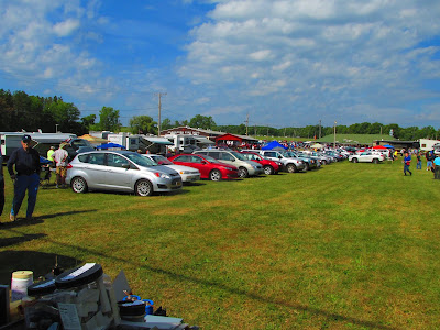
2018 Batavia NY Hamfest
I bought a "new to me" Canon SX160 camera at the Batavia Hamfest. It has 16x optical zoom (64x with digital) and 16 Megapixels. It also does great video. Here are some pictures I took with it.

There was some space for more vendors as seen in this picture. There were three isles of vendors. I was just testing the camera so I did not catch anything interesting.
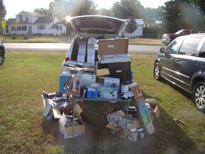
Now to get the pictures from my Sony camera that hopefully shows more vendors. Here is my carload of stuff for sale.
Here is a look down one of the isles of stuff for sale.


There was some space for more vendors as seen in this picture. There were three isles of vendors. I was just testing the camera so I did not catch anything interesting.

Now to get the pictures from my Sony camera that hopefully shows more vendors. Here is my carload of stuff for sale.

Here is a look down one of the isles of stuff for sale.

Monday, June 18, 2018
Here is a comparison of some of the amplifiers found on eBay.
I have been comparing the specifications of some of the amplifiers that I have worked with:
L-10 Amplifier:
Size: 200x41.5x?? mm
8 Ohm 100 Watts
4 Ohm 200 Watts
2 Ohm 350 Watts +-55VDC
Gain: ??
Output Transistors - 3 EA: A1943 C5200
 |
| L-15 Amplifier |
L-15 Amplifier:
Size: 150x40x?? mm
Size: 5.9x1.57x??"
8 Ohm 150 Watts
4 Ohm 300 Watts
2 Ohm 600 Watts +-55VDC
Gain: 36x
Output Transistors - 3 EA: IRFP240/IRFP9240
 |
| L-20 Amplifier |
L-20/28 Amplifier:
Size: 110x65mm (L-20)
8 Ohm 200 Watts +-65V
4 Ohm 350 Watts +-60V
2 Ohm
Gain: 34x
Output Transistors - 4 ea D1047 B817
Note: L-20-SE has 2SA1943 2SC5200 transistors
Note: L-28 Includes capacitors and speaker protection
 |
| PR-800 Amplifier |
PR-800 Amplifier:
Size: 245x65x30mm (or 195x90 with 4 Capacitors)
Size: 9.64x2.55x1.18"
8 Ohm 500 Watts +- 95VDC
4 Ohm 1000 Watts +-90VDC
2 Ohm 1000 Watts +-65VDC
Gain: 40x
Output Transistors - 4 ea TTA1943 TTC5200
Note: Includes Capacitors and Speaker protection
Note there are 2 sizes; one with 2 large filter capacitors and one with 4 large filter capacitors.
 |
| NJW0281/NJW0302 Amplifier |
NJW0281/NJW0302 450W+450W HIF
Size: 259x73mm
8 Ohm
4 Ohm 450 Watts +-85VDC
2 Ohm
Gain: Very Low - needs preamplifier
Output Transistors - 4 ea NJW0281/NJW0302
Note: ATX power supply pins fit the connectors on the right side.
Wednesday, June 13, 2018
Rebuilding some old speakers
I was given some speakers that I had built back in the 70's and that had been in use at a churhc for about 20 years or more. They were made to look nice, but I will rebuild them to look tough. I also want to upgrade them from 25 watts to about 150 watts or more.
This is what I bought at a Hamfest to rebuild the speakers with.

 Initially this is what initially had to work with. I only had one of these bass speakers.
 Here is one cabinet stripped down and the old speakers sitting on top of it.
 I painted the front plywood black and started reassembling the speakers. I traded something for some tweeters. They are rated at 75 watts. I also added some grills to protect the woofers.

This is what I bought at a Hamfest to rebuild the speakers with.

This picture compares an old speaker with one of the new ones.


Rebuilding LAB Series LS800 Amplifier with a PR-800 Amplifier
I had rebuilt this LS800 amplifier with a L-15 amplifier but I decided to upgrade to PR-800 amplifiers for much more power. This is a picture of the old amplifier dissembled.
 This is a picture the old power amplifier section. It was really cobbled.
 This is how the PR-800 amplifier boards arrived. Note that the power output transistors will have to be soldered on.
Here I have added the output power transistors. I also moved the driver transistors to the top side of the board for mounting on the heat sinks that I have. Their leads barely reach the tops of their holes.
This is what it looks like mounted on the heat sink. I went back and added washers under the heads of the 3/4 inch 4-40 screws. Note that little plastic washers must be installed in the two To-220 transistors (Q12 and Q15). Make sure to check for shorts to the heatsink with a voltmeter!
WARNING!! Something was really wrong, it tripped the circuit breaker and shorted the output transistors!!! I eventually found the problem. The 2SD669 (Center transistor Q13) has to be soldered UPSIDE DOWN on the top board!
Here is the schematic of the output section. Note that the 2SC5200 (Q16, Q17, Q18, Q19) transistors are connected to the + power source and the 2SA1943's (Q20, Q21, Q22, Q23) are connected to the negative power source. Also not that the two boards are the opposite of each other. The 2SA1943's will always be next to the power filter capacitors.

 Here is a labeled picture

I have both channels working fine now, but only one at a time.
As you can see I cut off one side of the heatsink. I also switched to silicone insulators because they are less messy. One channel is missing two power transistors because they were fried when I installed the 2SD669 right side up.
 This project is finally done! The cooling fan was mounted to the front cover to make working on the amps easier. The heatsinks were mounted to the bottom of the cabinet. The LM3915 LED VU meters have the bottom LED always on and the top two red ones are in parallel thus giving 12 LED's per channel.


 |
| Pr-800 as it arrives |
| PR-800 with power transistors |
 |
| PR-800 Mounted on heatsink |
| Upside Down Transistor on PR800 |

The schematic was derived from this schematic found on the internet. The protection circuits do not match what I received.


I have both channels working fine now, but only one at a time.
 |
| PR-800's mounted on heat sinks |


2018 Chaffee NY Hamfest
I was at the 2018 Chaffee NY Hamfest. It is a smaller one but I got some great deals. This is what it looked like. It is a smaller Hamfest but it is less than 5 miles away for me.


Friday, June 8, 2018
Niles ZR 4630 tear down and rebuild
A friend has a Niles ZR-4630 that he wants made into independent amplifiers. There are six stereo amplifiers based on the LM3886 IC. I have been reverse engineering it. By default the mute is "on" for the amplifier modules. Here are some pictures of the guts.
 This shows the amplifier modules and the power transformer. We could not get the power on by the on off switch so we hot wired power to the transformer.
 This is another view of the transformer and amplifiers.
 This is a view of the back side of the guts.
 So far I have been able to confirm the pins of the amplifiers. There is more to come.
 Here is a picture of one of the amplifiers running on the workbench.


Wednesday, May 23, 2018
Rebuilding LAB Series LS800 Amplifier with a L-15 Amplifier
I am rebuilding another power amplifier. This time I chose the L-15 amplifier because it fits in the heatsink.
The L 15 amplifier compared to the old circuit board for size.
 The amplifier totally dissembled into pieces.
 The back panel of the amplifier.
 Here is the ebay ad for the replacement amplifier.
 The L15 fits nicely in the heat sink
 I am using 4 pin power connectors for 5.25 floppy drives for power and ground. Red is positive, yellow is negative and black is ground.
 Here is a picture of the old front panel. I will replace it with two LM3915's.
 This is the first test. Power is at + and - 62 VDC. Lots of gain, I had to turn the volume way down. Still to go are the input jacks and volume controls.


The L 15 amplifier compared to the old circuit board for size.


I have been comparing some of the amplifiers that I have worked with:
L-10 Amplifier:
Size 200x41.5x?? mm
8 Ohm 100 Watts
4 Ohm 200 Watts
2 Ohm 350 Watts +-55VDC
Transistors 3 EA: A1943 C5200
L-15 Amplifier:
Size 150x40x?? mm
Size 5.9x1.57x??"
8 Ohm 150 Watts
4 Ohm 300 Watts
2 Ohm 600 Watts +-55VDC
Gain 36x
Transistors 3 EA: IRFP240/IRFP9240
L-20/28 Amplifier:
Size 110x65mm (L-20)
8 Ohm 200 Watts +-65V
4 Ohm 350 Watts +-60V
Gain 34x
Transistors 4 ea D1047 B817
Note: L-28 includes capacitors and speaker protection
PR-800 Amplifier:
Size 245x65x30mm (or 195x90 with 4 Capacitors)
Size 9.64x2.55x1.18"
8 Ohm 500 Watts +- 95VDC
4 Ohm 1000 Watts +-90VDC
2 Ohm 1000 Watts +-65VDC
Gain 40x
Transistors 4 ea TTA1943 TTC5200
Note: Includes Capacitors and Speaker protection
Note there are 2 sizes one with 2 capacitors and one with 4 capacitors.
NJW0281/NJW0302 450W+450W HIF
Size 259x73mm
8 Ohm
4 Ohm 450 Watts +-85VDC
Gain Very Low - needs preamplifier
Transistors 4 ea NJW0281/NJW0302
I think I can fit the PR-800 amplifier version with two filter capacitors so I will try to upgrade to that amplifier instead. It is coming from China so it will take a while. Please stay tuned. The PR-800 version is in another blog post.
I am rebuilding the VU meters. I did purchase some LM3915 kits but they only have 10 LED's and I have 12 holes to fill. I also used round LED's instead of the flat ones that came with the kit. But that version only has 10 LED's. So I stripped a board from the amplifier bare and installed a LM3915 instead leaving room for more circuitry.

However the rebuilt VU meter was barely visible! So I had to replace all of the LED's with newer brighter models. Now to add the two top LED's. I am planning on using a dual op amp for that job.
Subscribe to:
Posts (Atom)