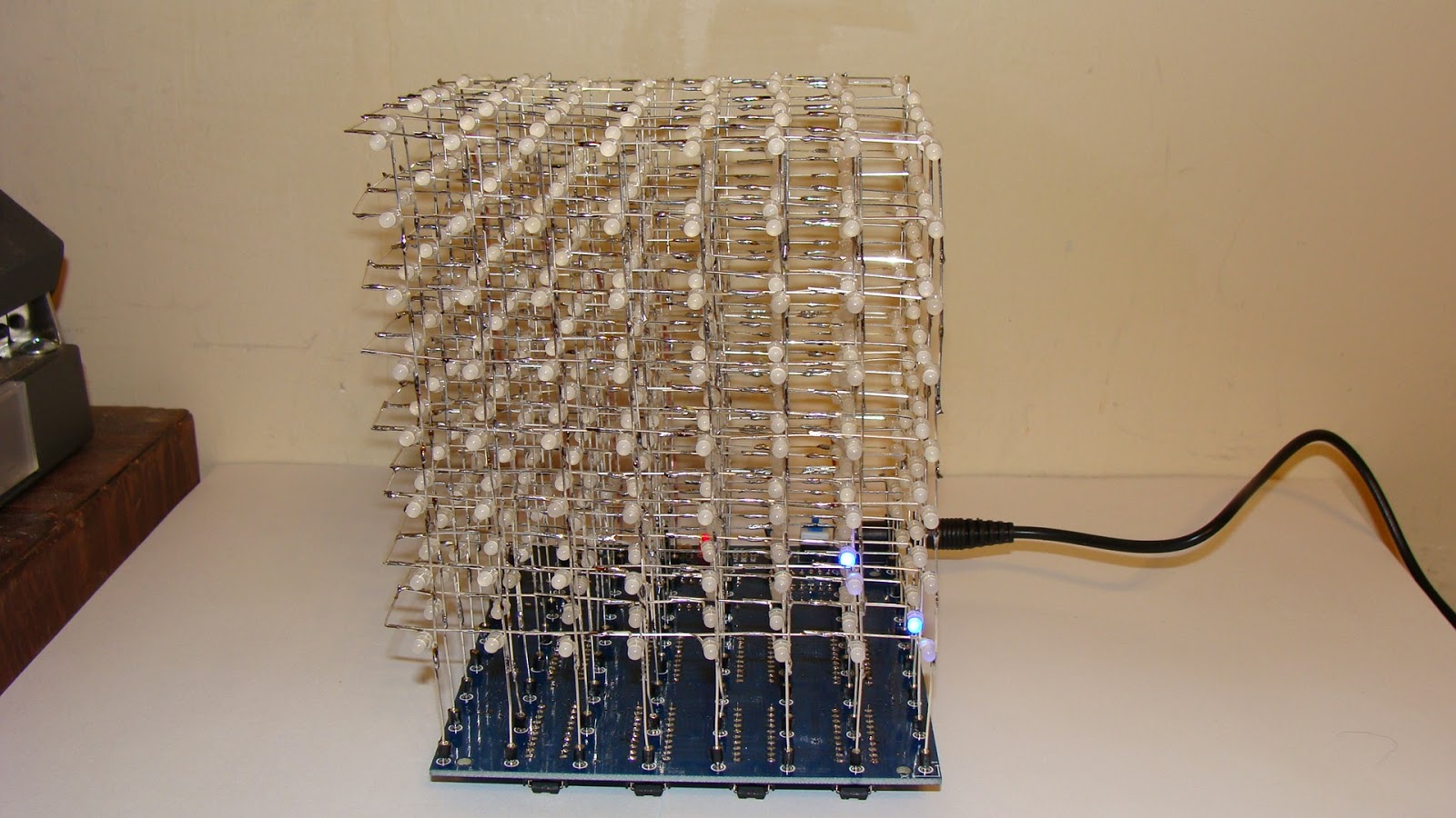
Here is the front view of the completed 8x8x8 LED cube kit.
This is the back view. You can see the wires going up to the eight layers.
Here is the bottom view so you can see the IC's.
This it the video of it on YouTube.
The design problem is that there should be a resistor in each LED leg, that would take 64 resistors. Instead they used 8 resistors in the common cathode circuit. As a result the brightness of each layer varies depending upon how many LED's are lit up. The more led's are lit the dimmer the layer becomes. I might try to fix this by adding a resistor on each of the 64 legs and removing the ones on the common cathode connection to each layer. If nothing else reducing the 500 ohm resistor to 100 or 220 ohms might do the trick.
Here is the quick fix - just change the 510 ohm resistors to 51 ohms. Then the display is much brighter. It is still not as bright as when I used 74595 shift registers.
I am now reverse engineering this LED cube to allow an Arduino to control it.
Here is the completed modification. It requires adding a 74LS138 IC. The latches need to be changed to 74HC574's to make it work properly with an Arduino.
This is the schematic diagram.
Here is a video of the cube kit working with the Arduino Uno.
Once it was interfaced to the Arduino I used a spare analog pin to add sound to it.
This is the schematic of the resulting cube:


16 comments:
Bob i have a question. I have built the same led cube you built from the same kit. All leds are working but in the wrong order. Were would you start troubleshooting? I have posted video of what my cube is doing on fb. My name it matt pickel. My profile picture is of the cartoon brain from pinky and the brain.
Is the reversed order bottom to top? If so it is the common cathode jumpers on the back side.
Hi there could you please show me how it is connected to the arduinother many thanks in advance
Connecting it to an Arduino requires an adapter. It is detailed in my book "Arduino LED Cube Projects"..
Hello,
Don't know if you will see this, but I'm new to reading schematics but it doesn't seem like the schematic matches the picture and the picture doesn't seem to match the youtube video. If it isn't too much to ask, could you tell me what the each white wire is actually connecting together? It's a little hard to tell.
Also, are 4 and 5 on the SN74L... connected and then connected to ground?
Is there anyway you can tell us what the wires are actually connecting. The picture looks different from the schematic. Or should I just follow the schematic?
Both the picture and schematic look correct to me? Where do they differ?
Bob, thank you for posting this information. I bought your book and it is very helpful for this retrofit.
I have a few amateur issues I was wondering if you could help me with. I have not started the retrofit yet so I have the original kit setup:
1. One entire layer (third row) is not lighting. I checked the ground connection to the chip/resistor and multimeter is showing good connections. I checked the layer itself if it works and all the LEDs light up. Lastly replaced the chip with a spare 573 but still didn't work. Any ideas?
2. I'm having ghosting issues on 3 layers. I checked the LED cube itself and checked the LEDs individually. I found that the LEDs worked independently but when hooked up to the board, 3 layers ghost. Do you have any ideas as to where on the board to check?
Thank you for your time. Hope to let you know if the retrofit works on my end.
RachelM - I cannot figure out the problems from the descriptions. However the layers interact in strange ways. If a LED is bad in a layer it can affect the entire layer. Perhaps picture would help? -Bob
hello bob, I have a question, exactly why we have to change the 74hc753 by the 74hc754 ic´s?
Hello Bob can I ask you some questions?
1-exacly why did you replaced the 74hc573 whit the 74hc574
2-what's the use of the resistor array?, I don't see any important role of this part in the circuit
Thanks for your attention
The 74HC374 is a latch, it works best with the latch selector. The 74HC573 is a transparent latch that allows noise through, like changing the data bits, when transparent.
The resistors make the display much brighter.
Hello Bob! Looks like you are the man I have been looking for! I have assembled a cube exactly as you have above but when I switched it on I just get 10 static columns illuminated in the shape of a 0, if looking top down on the cube. No transitions at all. Do you have any idea where I should look to debug this?
I will be investing in your book as want to get this hooked up to an arduino but first need to get the thing working!
Any help would be greatly appreciated.
Tim
I do not know what would cause that problem. Check to make sure all the IC's are oriented correctly? -Bob
Hello Bob. I've install components, but when tested, I'm only getting .4v at all header pins. Main power led Cube s coming on and I have normal voltage power jack, but losing after there...please help.
Roycon, I am not sure what you mean by "header pins" but a DC voltmeter will not see the pulses. -Bob
Post a Comment