I have been wrining a book of "Arduino Oscilloscope Projects". In this book I show 4 different LCD's, 5 different Analog to digital converters, and 3 different analog front ends. The code has greatly improved with a "gain" in software feature. I have written the code for a 1.8 SPI TFT screen as well as for a 2.4 inch or 2.8 inch ILI9341 Screen.
Here is what the 1.8 inch screen looks like. On the bigger screens the sample time in MS is located under the other text fields on the right side.
Here is what the assembled oscilloscope looks like so far.
This is a picture of the main board without the LCD screen.
This is the front cover. I need to wire the cover to the main board next.
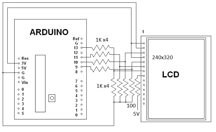
Over the weekend I figured out how to interface a 2.8 inch SPI TFT that has a ILI9341 chip to an Arduino Uno. All it takes is eight 1K resistors. Most people use a 4050 IC. Here is the schematic.
I am using the Adafruit ILI9341 driver found at: https://github.com/adafruit/Adafruit_ILI9341
Note that the Adafruit LCD has level shifters for 5 volts built into it.
Here is a video of it working on Youtube.
Here is a video of the LCD being used as an oscilloscope.
Here are a couple of still pictures, only 6 of the 8 bits are connected for these pictures.
Here is the code for a more basic oscilloscope.
/************************************
2.8 SPI PIND TFT Oscope Simple
Reads the D0-D7 pins using PIND,
and shows the value on the screen.
Created 27 july 2015 by Bob Davis
**************************************/
//#include // Arduino LCD library
#include
#include "Adafruit_ILI9341.h"
#include "Adafruit_GFX.h"
// pin definition for the Uno LCD
#define TFT_DC 9
#define TFT_CS 10
// Use hardware SPI (on Uno, #13=clk, #11=mosi) and the above for CS/DC
//Adafruit_ILI9341 tft = Adafruit_ILI9341(TFT_CS, TFT_DC);
Adafruit_ILI9341 tft = Adafruit_ILI9341();
//// set up variables
int Input=0;
byte Sample[320];
int trigger=64;
void setup(){
// initialize rotate and clear the display
tft.begin();
tft.fillScreen(ILI9341_BLACK);
tft.setRotation(1);
// Set the font size
tft.setTextSize(2);
// D input pins
pinMode(0, INPUT);
pinMode(1, INPUT);
pinMode(2, INPUT);
pinMode(3, INPUT);
pinMode(4, INPUT);
pinMode(5, INPUT);
pinMode(6, INPUT);
pinMode(7, INPUT);
}
void loop(){
// wait for a positive going trigger
for (int timeout=0; timeout < 1000; timeout++){
Input = PIND;
if (Input < trigger) break; }
for (int timeout=0; timeout < 1000; timeout++){
Input = PIND;
if (Input > trigger) break; }
// quickly collect the data with no delay
for (int xpos=0; xpos <320; xpos++){ Sample[xpos]=PIND;
// display the collected data
for (int xpos=0; xpos <319; xpos++){
// erase the old and draw new line
tft.drawLine(xpos+1, 0, xpos+1, 240, ILI9341_BLACK);
tft.drawLine(xpos, (Sample[xpos]*2), xpos+1, Sample[xpos+1]*2, ILI9341_WHITE);
}
}
// End of program
This year I made it back to the Batavia NY Hamfest! It was bigger than most of the Hamfests that I make it to. The picture only shows one of two isles of equipment for sale. I forgot my camera and it was dark so my cell phone pictures are not that great, sorry about that.
Here is my stuff for sale. The car does not fit as much stuff as the van did.
My book "Arduino Robotics Projects" ended with a walking dinosaur. I might eventually write a sequel to that book with a spider and a humanoid robot. One of those projects that I have been working on is a walking "Humanoid" robot. Recently I completed building the legs.
Here are some of the many parts that comes with the robot found on ebay.
Here is the actual parts list:
- 16 x Multi-functional servo bracket
- 7 x Short U-type servo bracket - 4 x Long U-type servo bracket - 4 x Angled U-type servo bracket - 4 x Flat servo bracket - 4 x L-type servo bracket - 1 x U-type robot waist bracket (not pictured, I made my own) - 2 x Foot Base - 14 x Miniature Ball Radial Bearing - 17 x Metal Servo Horn Flange - 1 x Screw and nut set
You will also need flanges, bearings and lots of screws. Do not use the pictured 16 channel servo controller you will need a 32 channel servo controller.
You will also need about 17 servo motors! Here is a few of them, they are MG995's.
Here is how to assemble the feet. Use the flat head M4 screws as seen on the right side.
There are two ways to mount the bearing as seen on the left in the above picture. You can put the screw in first and then bend the "U" metal bracket over the screw and bearing. The other way is to use tweezers to hold the nut in place and then put the screw in as seen above.
When I started I used the wrong screws to hold the servo's in place. You are supposed to use the M4 screws (A little bigger than a 6-32 screw) but I used the M3 screws (about the size of a 4-40 screw) instead. I am in the process of changing all of the servo mounting screws. Also my guess is that the four screws used to hold the servo flange to the "U" bracket are supposed to be flat head screws. The rounded or pan head screws are for the center of the flange to fasten it to the servo.
I am making my own breast plate that looks better than one made out of small parts. It is made out of a left over 4 inch piece of 3 inch "C" channel removed from a 19 inch rack.
Here is the completed and painted chest piece.
I have assembled the robot with the home made chest. I used 1/2 inch spacers to move the shoulder servo's out to where the head mounting bracket fits between them. Note that I only used 4 servo's per leg, I think that is all that is needed.
Last night I was testing a TDA8703 analog to digital converter and after trying 36 MHz I tried 50 MHz on a whim and it worked. I also tried 60 MHz but the TDA8703 flaked off at that speed.
I have been testing various fast analog to digital converters with the Arduino. There are two objectives. I want to see if I can improve the old CA3306 version by getting rid of the glitches. I want to add a FIFO that can push past 10MSPS as that was the fastest rate achieved previously.
The first picture is of a rebuilt version of the CA3306 circuit.
Next I tried a TLC5510. The results were a bit noisy as seen in the next picture.
A picture of the TLC5510 screen. The noise might not be the fault of the A to D converter. The noise was cured by synchronizing the clocks.
TDA8703 Analog to Digital converter being tested. At first it did not work until I increased the power from 4.2 volts (from USB) to 5 volts via an AC adapter.
I found a way to synchronize the clocks and thus reduce the amount of glitches! Here is the video.
Here is a Youtube video showing the TLC5510 running without the clock glitches.
Here is a video showing a completed Arduino Oscilloscope with working selection switches.
Now in light of that, the banning of the confederate flag makes sense! Why ban the confederate flag while allowing the swastika and the ISIS flags to be sold? Simple, they know the second civil war is coming and they want to stop it. Now first of all lets get our facts right. The civil war was not just about slavery! It is called the "confederate flag" because they were against "con" the "federate" or federal powers. You see the federal government was usurping too much power and some states wanted out of the union. The other army was called the "Union" army for the opposite reason, they wanted to keep the union of the states. So, now do you see why they are banning the confederate flag?
Why are we not fighting ISIS? It is for the same reason. The federal government needs to keep lots of troops here in the US to "keep the peace" while it continues to usurp way too much power. Enter "Jade Helm" a "military exercise" throughout the southern (confederate) states. This excuse allows the federal government to flood the confederate states with troops ready to fight to keep government control of those states.
I know this sounds like a bunch of conspiracy theories but unfortunately it has become reality.
Now add the upcoming stock market crash. As the Greece economy collapses, France, Italy and Puerto Rico are also on the verge of bankruptcy. The 18 trillion dollar debt this country owes is only the tip of the iceberg. Internationally there is over 160 trillion in debt. You can keep borrowing to pay the debt and "Kick the can down the road" for only so long. Sooner or later the debt has to be paid. If all of the money that is printed in the world was all bought together in one pile it could not even pay a fraction of the total debt!
So again I propose a solution. Dissolve the US and split it into smaller countries - as in the second civil war. If the US does not exist then its debts do not exist. In any case this massive debt is going to lead to a lot of countries into declaring bankruptcy.
Also this whole "gay marriage" thing is not just about gay marriage. It is about legitimatizing the homosexual lifestyle. Just as abortion made "sleeping around" more legitimate, "gay marriage" makes being gay more "legitimate". Only less than .1% of the population have had a 'gay marriage".
I am finishing up the biggest project for my latest book on LED cubes. Here are a couple of video's about the 8x8x8 color LED cube.
In this first video it was just 7x7x2 in size:
In this next video it is up to 7x7x4 in size and still growing as more LED's arrive:
It has now grown to 8x8x4 in size.
I will have to use a pad per hole soldered breadboard to proceed any further. The 7x7x4 setup takes over 200 jumpers to connect everything. I would buy a printed circuit board but as far as I know no one makes one that meets my standards! The closest design I have found uses latches and lots of transistors and resistors. My design uses nothing but 74HC595 shift registers and a ULN2803.
Here are the red, green, blue and white test pictures.
And now the schematic for one layer...
Someone pointed out that the resistor values are not given in the schematic above. You can use from 47 to 100 ohms, I was using 51 ohm resistors.
I was at a yard sale and I asked them about a 32 inch TV. They said it was free because the screen did not light up. It turned out to be the same model and have the same problem that I have diagnosed before. It was bad capacitors in the HV power supply for the backlight.
Here is a picture of the bad 10 uF at 450 volt capacitors.
I replace them with 2 or 4 uF at 400 volt paper capacitors. There is a hole pattern already there for the larger capacitors. This picture shows the old holes and the new holes to use.
Here is what the new capacitors look like installed on the High Voltage power supply.
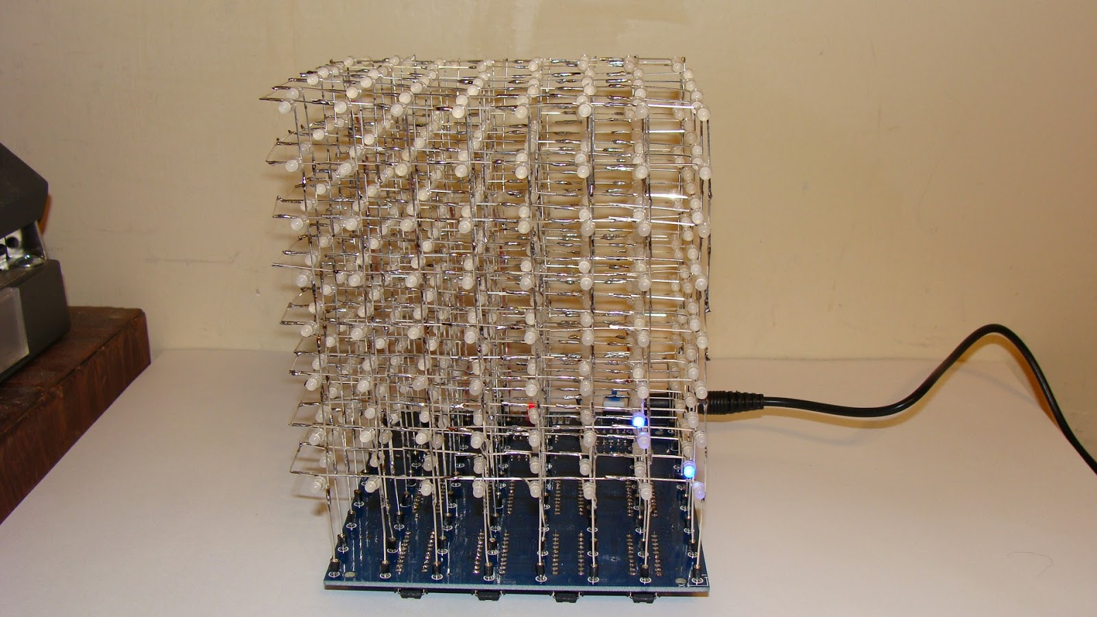
I completed the third application for my 8x8x8 LED cube. First it was to use it with an Arduino, then with a Raspberry Pi and then this kit that I bought on eBay. At first I thought it was not working because it is so dim that you have to turn down the lights to watch it. Once that problem was fixed I then reverse engineered it to work with an Arduino once again.
Here is the front view of the completed 8x8x8 LED cube kit.
This is the back view. You can see the wires going up to the eight layers.
Here is the bottom view so you can see the IC's.
This it the video of it on YouTube.
The design problem is that there should be a resistor in each LED leg, that would take 64 resistors. Instead they used 8 resistors in the common cathode circuit. As a result the brightness of each layer varies depending upon how many LED's are lit up. The more led's are lit the dimmer the layer becomes. I might try to fix this by adding a resistor on each of the 64 legs and removing the ones on the common cathode connection to each layer. If nothing else reducing the 500 ohm resistor to 100 or 220 ohms might do the trick.
Here is the quick fix - just change the 510 ohm resistors to 51 ohms. Then the display is much brighter. It is still not as bright as when I used 74595 shift registers.
I am now reverse engineering this LED cube to allow an Arduino to control it.
Here is the completed modification. It requires adding a 74LS138 IC. The latches need to be changed to 74HC574's to make it work properly with an Arduino.
This is the schematic diagram.
Here is a video of the cube kit working with the Arduino Uno.
Once it was interfaced to the Arduino I used a spare analog pin to add sound to it.