This post is continued here:
http://www.bobdavis321.blogspot.com/2013/01/signature-electronic-signs-convert-to.html
There are several Signature Electronic LED Signs for sale on EBay. I bought one that did not work and to get it working I had to add a power cord, and connect the 5 volt power to the processor board in the upper left corner.
Here is the right side of the back where the 110 Volt power is connected.
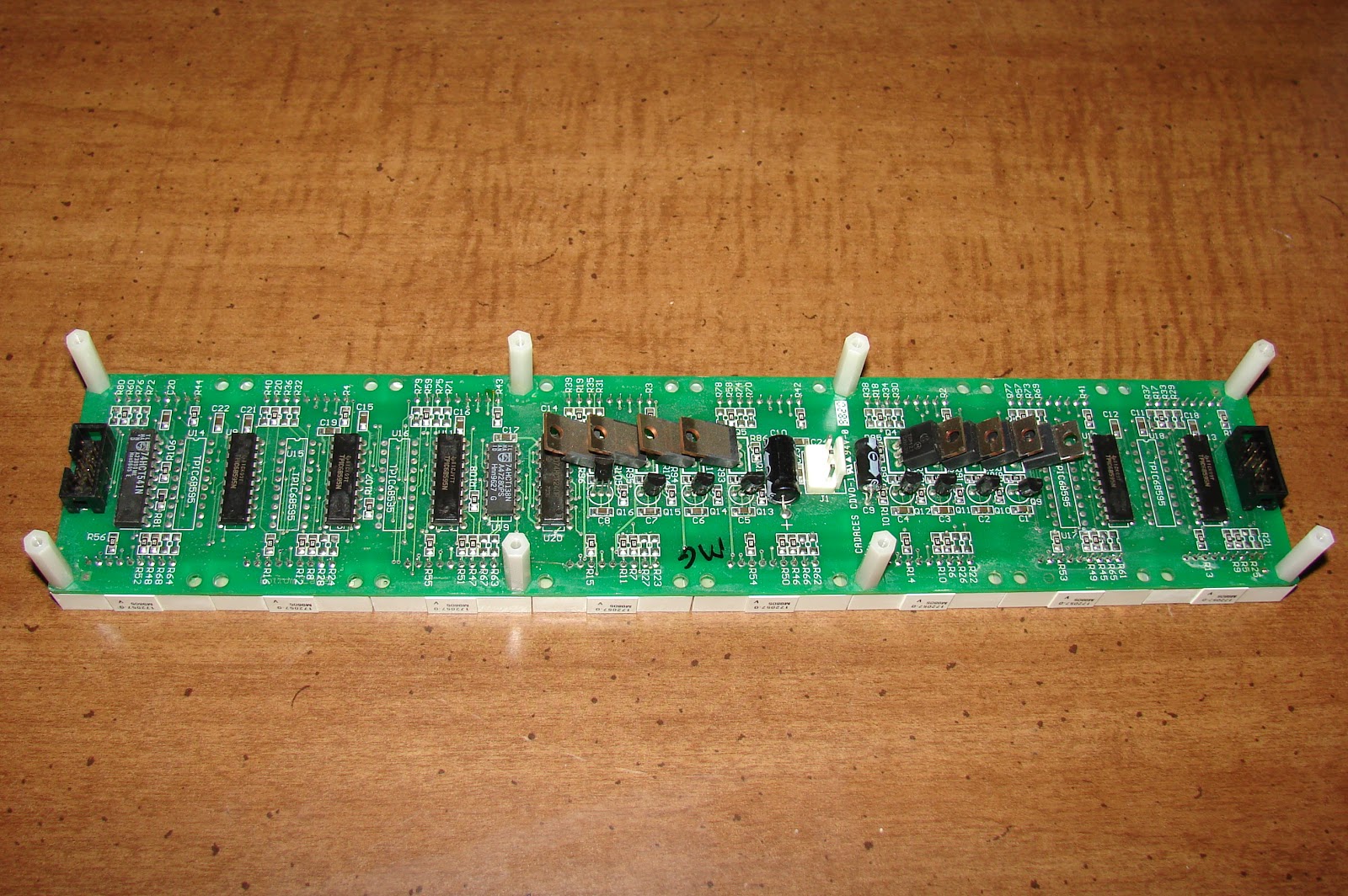
These signs are made with Cadaces CDVO-1 boards strung together. Each of those boards holds 8 of 8 by 5 LED arrays. TPIC68595 serial shift registers drive the columns and a 74HCT138 drives the rows via some TIP127's. There are 12 of these Cadaces CDVO-1 boards in the sign.
The controller card has two wires that connect it to the outside world. One is green one is blue. I have traced them out to a "485" IC. That IC is a RS422 communications chip, so likely the sign is communicated with via RS422. You will need a Serial or USB to RS422 adapter to talk to the sign.
Here is what one of the Cadaces CDVO-1 boards looks like.
Here is the back side of the Cadaces CDVO-1 board. I have metered out the pinout and hope to post that soon. Then I can work on interfacing it to an Arduino or something like that.
Here is how the Cadaces board connects to the controller.
Here is a size comparison between the new sign and the old Silent radio sign
The new sign is now working with the Arduino processor, but there is a bug when trying to run the entire sign. Each sequential board displays the same thing as the previous board, it is just scrolled down one position.
I am using the same software as with the Silent Radio sign, but with the register clock jumpered to the serial data clock, and the column selection code has been modified to work with the 74138.