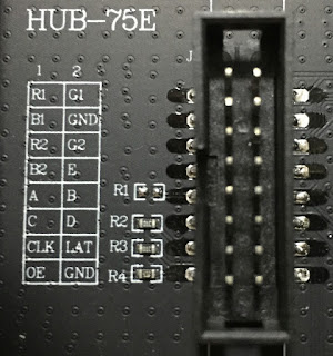
Here is a picture of the HUB75 connector from someone else on the Internet. Note the "E" pin in the middle right of the pin listing.
So far I can only get it to turn all white or half white. I am working on my own code since all the drivers out there are insanely complex!
This picture shows the mod to connect E (Located between B and G2) to A4, using the lower yellow jumper wire. The upper yellow jumper is for the clock to go to D8 or to D11 for use with the Mega.
This is the first video of it starting to work:
Here is a video of THREE 64x32 panels working with an Arduino UNO.
This video shows three panels with different text and background colors.
This is a picture of the display with some different color backgrounds.
The FM6126A Spec sheet tells how the chip is not just a normal shift register. This was translated from the Chinese manual with google translate. Basically the number of clock pulses while the LE (Latch Enable) is high tells the shift register what to do. Three clock pulses are required to latch and display the data. No clock pulses resets the display to blank. That explains why most demo programs come up with a blank display. Eleven or twelve clock pulses access the control registers. Some people say you can set all the data for the control registers to high and that works.
Instruction LE Instruction Description
--------------- --- ----------------------------
RESET_OEN 0-1 Soft reset signal
DATA_LATCH 3 latches 16 bit data to the output
-- 4~10 Reserved
WR_REG1 11 Write configuration register 1
WR_REG2 12 Write configuration register 2
Remark: The length of LE refers to the number of rising edges of CLK when LE is high. As shown in the figure below, the length of the first LE signal is 3, which is the "Data_Latch" command.
Here is two of the panels working with a Raspberry Pi after running resetmatrix.py
This is the Raspberry Pi VU meter demo program;
This is the back side of one of the LED panels;
My Arduino code is now compatable with the Adafruit demos!
Here is the Youtube Video:
Now some pictures of the demo's running, the first two are called "Plasma"
This is the "Test Shapes" demo:
// 128x32 Uno LED panel driver
// Fast Clock Mod
// 3/4/2019 by Bob Davis
// #define A A0 // Port D assignments
// #define B A1
// #define C A2
// #define D A3
// #define E A4
// #define CLK 8 // Port B assignments
// #define OE 9
// #define LAT 10
int C12[16] = {0,1,1,1,1,1,1,1,1,1,1,1,1,1,1,1};
int C13[16] = {0,0,0,0,0,0,0,0,0,1,0,0,0,0,0,0};
#define MaxLed 128
byte BGC1=0x04; // Background
byte FGC1=0x1C; // Foreground
byte BGC2=0x20; // Background
byte FGC2=0xE0; // Foreground
#define PIXEL_PORT PORTD // Port the pixels are connected to
#define PIXEL_DDR DDRD // D2-D7
#define ROW_PORT PORTC // Port the rows are connected to
#define ROW_DDR DDRC // A0-A5
#define CLK_PORT PORTB // Port the Clock/LE/OE are connected to
#define CLK_DDR DDRB // D8-D10
char text1[]="ARDUINO UNO RUNS ";
char text2[]="TWO 64X32 PANELS ";
// This font from http://sunge.awardspace.com/glcd-sd/node4.html
byte font[][7] = {
0x00,0x00,0x00,0x00,0x00,0x00,0x00, // ascii 32
0x00,0x00,0xfa,0x00,0x00,0x00,0x00, // !
0x00,0xe0,0x00,0xe0,0x00,0x00,0x00, // "
0x28,0xfe,0x28,0xfe,0x28,0x00,0x00, // #
0x00,0x34,0xfe,0x58,0x00,0x00,0x00, // $
0xc4,0xc8,0x10,0x26,0x46,0x00,0x00, // %
0x6c,0x92,0xaa,0x44,0x0a,0x00,0x00, // &
0x00,0xa0,0xc0,0x00,0x00,0x00,0x00, // '
0x00,0x38,0x44,0x82,0x00,0x00,0x00, // (
0x00,0x82,0x44,0x38,0x00,0x00,0x00, // )
0x10,0x54,0x38,0x54,0x10,0x00,0x00, // *
0x10,0x10,0x7c,0x10,0x10,0x00,0x00, // +
0x00,0x0a,0x0c,0x00,0x00,0x00,0x00, // ,
0x10,0x10,0x10,0x10,0x10,0x00,0x00, // -
0x00,0x06,0x06,0x00,0x00,0x00,0x00, // .
0x04,0x08,0x10,0x20,0x40,0x00,0x00, // /
0x7c,0x8a,0x92,0xa2,0x7c,0x00,0x00, // 0
0x00,0x42,0xfe,0x02,0x00,0x00,0x00, // 1
0x42,0x86,0x8a,0x92,0x62,0x00,0x00, // 2
0x84,0x82,0xa2,0xd2,0x8c,0x00,0x00, // 3
0x18,0x28,0x48,0xfe,0x08,0x00,0x00, // 4
0xe4,0xa2,0xa2,0xa2,0x9c,0x00,0x00, // 5
0x3c,0x52,0x92,0x92,0x0c,0x00,0x00, // 6
0x80,0x8e,0x90,0xa0,0xc0,0x00,0x00, // 7
0x6c,0x92,0x92,0x92,0x6c,0x00,0x00, // 8
0x60,0x92,0x92,0x94,0x78,0x00,0x00, // 9
0x00,0x6c,0x6c,0x00,0x00,0x00,0x00, // :
0x00,0x6a,0x6c,0x00,0x00,0x00,0x00, // ;
0x00,0x10,0x28,0x44,0x82,0x00,0x00, // <
0x28,0x28,0x28,0x28,0x28,0x00,0x00, // =
0x82,0x44,0x28,0x10,0x00,0x00,0x00, // >
0x40,0x80,0x8a,0x90,0x60,0x00,0x00, // ?
0x4c,0x92,0x9e,0x82,0x7c,0x00,0x00, // @
0x7e,0x90,0x90,0x90,0x7e,0x00,0x00, // A
0xfe,0x92,0x92,0x92,0x6c,0x00,0x00, // B
0x7c,0x82,0x82,0x82,0x44,0x00,0x00, // C
0xfe,0x82,0x82,0x82,0x7c,0x00,0x00, // D
0xfe,0x92,0x92,0x92,0x82,0x00,0x00, // E
0xfe,0x90,0x90,0x80,0x80,0x00,0x00, // F
0x7c,0x82,0x82,0x8a,0x4c,0x00,0x00, // G
0xfe,0x10,0x10,0x10,0xfe,0x00,0x00, // H
0x00,0x82,0xfe,0x82,0x00,0x00,0x00, // I
0x04,0x02,0x82,0xfc,0x80,0x00,0x00, // J
0xfe,0x10,0x28,0x44,0x82,0x00,0x00, // K
0xfe,0x02,0x02,0x02,0x02,0x00,0x00, // L
0xfe,0x40,0x20,0x40,0xfe,0x00,0x00, // M
0xfe,0x20,0x10,0x08,0xfe,0x00,0x00, // N
0x7c,0x82,0x82,0x82,0x7c,0x00,0x00, // O
0xfe,0x90,0x90,0x90,0x60,0x00,0x00, // P
0x7c,0x82,0x8a,0x84,0x7a,0x00,0x00, // Q
0xfe,0x90,0x98,0x94,0x62,0x00,0x00, // R
0x62,0x92,0x92,0x92,0x8c,0x00,0x00, // S
0x80,0x80,0xfe,0x80,0x80,0x00,0x00, // T
0xfc,0x02,0x02,0x02,0xfc,0x00,0x00, // U
0xf8,0x04,0x02,0x04,0xf8,0x00,0x00, // V
0xfe,0x04,0x18,0x04,0xfe,0x00,0x00, // W
0xc6,0x28,0x10,0x28,0xc6,0x00,0x00, // X
0xc0,0x20,0x1e,0x20,0xc0,0x00,0x00, // Y
0x86,0x8a,0x92,0xa2,0xc2,0x00,0x00, // Z
};
void setup() {
PIXEL_DDR = 0xFF; // Set all pixel pins to output
ROW_DDR = 0xFF; // Set all row pins to output
CLK_DDR = 0xFF; // Set all CLK/LE/OE pins to output
PORTB=0;
// Send Data to control register 11
for (int l=0; l<MaxLed; l++){
int y=l%16;
PORTD = 0x00;
if (C12[y]==1) PORTD=0xFC;
if (l>MaxLed-12){ PORTB=7; PORTB=6; }
else{ PORTB=1; PORTB=0; }
}
PORTB=0;
// Send Data to control register 12
for (int l=0; l<MaxLed; l++){
int y=l%16;
PORTD = 0x00;
if (C13[y]==1) PORTD=0xFC;
if (l>MaxLed-13){ PORTB=7; PORTB=6; }
else{ PORTB=1; PORTB=0; }
}
PORTB=0;
}
void loop() {
for (int c=0; c<600; c++){
if (c > 000){BGC1=0x04; BGC2=0x20; FGC1=0x1C; FGC2=0xE0;}
if (c > 200){BGC1=0x08; BGC2=0x40; FGC1=0x1C; FGC2=0xE0;}
if (c > 400){BGC1=0x10; BGC2=0x80; FGC1=0x1C; FGC2=0xE0;}
// Select the Row
for (int r=0; r<16; r++){
for (int l=0; l<MaxLed; l++){
int y=l%8; // remainder after division
int pd1 = BGC1;
int pd2 = BGC2;
if (y < 6){
if ((font[text1[l/8]-32][y] >> 8-r/2) & 0x01==1) pd1=FGC1;
if ((font[text2[l/8]-32][y] >> 8-r/2) & 0x01==1) pd2=FGC2;
PORTD=pd1+pd2;
}
if (l<MaxLed-3) {PORTB=1; PORTB=0;}
else {PORTB=7; PORTB=6;}
}
PORTC=r; // Update row
PORTB=0;
}
}
}


