Tuesday, January 29, 2013

Signature Electronic Sign to Arduino Part 3

Several people have asked for more information on the Arduino to Cadaces/Signature Electronics Sign interface. So I am posting a third time on the interface.

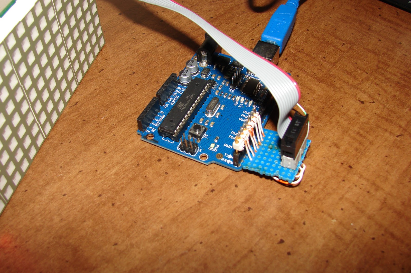
This is the schematic for a single line interface. It can run three cadaces modules, perhaps four. If you get garbage in your display, use shorter ribbon cables.This schematic is from the top side looking down at the adapter board.
This is a picture of the bottom of the interface board.
Here is a front view showing the adapter plugged into the left side of the Arduino.
This is a top view of the adapter board.
Here is the code for running two cadaces modules:
//****************************************************//
//  Name    : Cadaces Driver                          //
//  Author  : Bob Davis                               //
//  Date    : 4 January, 2013                         //
//  Version : 1.0                                     //
//****************************************************//
// Pins for the row drivers
int row1Pin = 1;
int row2Pin = 2;
int row3Pin = 3;
int rowEnable = 4;

// Pins for column shift registers
int rclockPin = 5;
int clockPin = 6;
int dataPin = 7;

// Set the pins to output to the sign
void setup() {
  pinMode(row1Pin, OUTPUT);
  pinMode(row2Pin, OUTPUT);
  pinMode(row3Pin, OUTPUT);
  pinMode(rowEnable, OUTPUT);
  pinMode(rclockPin, OUTPUT);
  pinMode(clockPin, OUTPUT);
  pinMode(dataPin, OUTPUT);
}

//=== Character Array ===
// Characters are A, B, C, etc.  Only upper case, no symbols.
byte alphabets[][8] = {
  {0, 04, 10, 17, 17, 31, 17, 17}, //A
  {0, 30, 17, 17, 30, 17, 17, 30}, //B
  {0, 14, 17, 16, 16, 16, 17, 14}, //C
  {0, 28, 18, 17, 17, 17, 18, 28}, //D
  {0, 31, 16, 16, 31, 16, 16, 31}, //E
  {0, 31, 16, 16, 31, 16, 16, 16}, //F
  {0, 14, 17, 16, 16, 19, 17, 14}, //G
  {0, 17, 17, 17, 31, 17, 17, 17}, //H
  {0, 14, 04, 04, 04, 04, 04, 14}, //I
  {0, 07, 02, 02, 02, 02, 10, 14}, //J
  {0, 17, 18, 20, 24, 20, 18, 17}, //K
  {0, 16, 16, 16, 16, 16, 16, 31}, //L
  {0, 10, 21, 21, 21, 17, 17, 17}, //M
  {0, 17, 25, 25, 21, 19, 19, 17}, //N
  {0, 14, 17, 17, 17, 17, 17, 14}, //O
  {0, 30, 17, 17, 30, 16, 16, 16}, //P
  {0, 14, 17, 17, 17, 17, 19, 15}, //Q
  {0, 30, 17, 17, 30, 20, 18, 17}, //R
  {0, 14, 17, 16, 14, 01, 17, 14}, //S
  {0, 31, 04, 04, 04, 04, 04, 04}, //T
  {0, 17, 17, 17, 17, 17, 17, 14}, //U
  {0, 17, 17, 17, 10, 10, 10, 04}, //V
  {0, 17, 17, 17, 21, 21, 21, 10}, //W
  {0, 17, 17, 10, 04, 10, 17, 17}, //X
  {0, 17, 10, 10, 04, 04, 04, 04}, //Y
  {0, 31, 8, 04, 02, 04, 8, 31}, //Z
};
byte bitmap[][8] = {
  {0, 0,0,0,0,0,0,0},
  {0, 0,0,0,0,0,0,0},
  {0,  4, 10, 17, 17, 31, 17, 17}, //A
  {0, 30, 17, 17, 30, 20, 18, 17}, //R
  {0, 28, 18, 17, 17, 17, 18, 28}, //D
  {0, 17, 17, 17, 17, 17, 17, 14}, //U
  {0, 14, 04, 04, 04, 04, 04, 14}, //I
  {0, 17, 25, 25, 21, 19, 19, 17}, //N
  {0, 14, 17, 17, 17, 17, 17, 14}, //O
  {0, 0,0,0,0,0,0,0},
  {0, 0,0,0,0,0,0,0},
};

void RunSign()
{
  for (int row = 7; row > 0; row--)
  {
    // turn off display
    digitalWrite(rowEnable, HIGH);
    // send serial data to display 10 = number of led arrays
    for (int character = 0; character < 11; character++)
    {
    shiftOut(dataPin, clockPin, MSBFIRST, bitmap[character][row]);
    }
    //latch the data
    digitalWrite(rclockPin, LOW); digitalWrite(rclockPin, HIGH);
    // set up 74138 row sesection and turn display back on
    digitalWrite(row1Pin, LOW);
    digitalWrite(row2Pin, LOW);
    digitalWrite(row3Pin, LOW);
    if (row==1 or row==3 or row==5 or row==7) digitalWrite (row1Pin, HIGH);
    if (row==2 or row==3 or row==6 or row==7) digitalWrite (row2Pin, HIGH);
    if (row >= 4) digitalWrite (row3Pin, HIGH);
    digitalWrite(rowEnable, LOW);
    // Wait to see what we sent to the display ;
    delayMicroseconds(500);
  }
}

//=== L O O P ===
void loop() {
  RunSign();


Tuesday, January 15, 2013

Acer Aspire 5560 repair

My brother sent me a dead Acer Aspire 5560 laptop.  I checked the power adapter and it had 19 volts.  I tried another adapter just in case, but it did not help either.  However after hearing that the problem is usually the AC adapter I bought another one on eBay and it fixed the laptop!

However the cooling fan in this laptop did need cleaning after only one year of use.  There is one trick in dissembling it.  Remove the CD rom drive, and reach inside to find a hole to push up on the keyboard.  Then push in the 4 catches located at the top of the keyboard.


This is the back side of the motherboard. You can see the three screws that hold the cooling fan together. Remove them and clean out the fan.

Monday, January 7, 2013

Signature Electronic Signs - convert to Arduino

I have removed three of the Cadaces modules and have written some new code to make them work.  Next is to hard wire the interface circuitry instead of using jumper wires.

Once the controller is wired up and the sign is put back together here is what it looks like.  The picture does not tell the whole story, the display blinks, and the more lines that are enabled the more it blinks.  I will have to work on improving the software to fix that problem.
Here is the new Arduino controller on the left compared to the old sign controller on the right:
Here is the Arduino Controller installed into the Signature Electronic Sign.  I goofed a little bit in the layout so that the ribbon cables must be flipped around backwards so that the stripe is to the right.
Here is the schematic diagram.  I wired it with point to point wiring, however a circuit board or wire wrap would have been easier to do.
Last of all here is the code for the sign.  It was written without scrolling and set up for up to four lines of text.  It still needs some work, like the ability to convert a line of text into an array of characters automatically.  I did that manually.

//****************************************************//
//  Name    : Cadaces Driver                          //
//  Author  : Bob Davis                               //
//  Date    : 4 January, 2013                         //
//  Version : 1.0                                     //
//****************************************************//
// Pins for the row drivers
int row1Pin = 1;
int row2Pin = 2;
int row3Pin = 3;
int rowEnable = 4;

// Pins for column shift registers
int rclockPin = 5;
int clockPin = 6;
int dataPin = 7;
int clockPin1 = 8;
int dataPin1 = 9;
int clockPin2 = 10;
int dataPin2 = 11;
int clockPin3 = 12;
int dataPin3 = 13;

// Set the pins to output to the sign
void setup() {
  pinMode(row1Pin, OUTPUT);
  pinMode(row2Pin, OUTPUT);
  pinMode(row3Pin, OUTPUT);
  pinMode(rowEnable, OUTPUT);
  pinMode(rclockPin, OUTPUT);
  pinMode(clockPin, OUTPUT);
  pinMode(dataPin, OUTPUT);
  pinMode(clockPin1, OUTPUT);
  pinMode(dataPin1, OUTPUT);
  pinMode(clockPin2, OUTPUT);
  pinMode(dataPin2, OUTPUT);
  pinMode(clockPin3, OUTPUT);
  pinMode(dataPin3, OUTPUT);
}

//=== Character Array ===
// Characters are A, B, C, etc.  Only upper case, no symbols. 
byte alphabets[][8] = {
  {0, 04, 10, 17, 17, 31, 17, 17}, //A
  {0, 30, 17, 17, 30, 17, 17, 30}, //B
  {0, 14, 17, 16, 16, 16, 17, 14}, //C
  {0, 28, 18, 17, 17, 17, 18, 28}, //D
  {0, 31, 16, 16, 31, 16, 16, 31}, //E
  {0, 31, 16, 16, 31, 16, 16, 16}, //F
  {0, 14, 17, 16, 16, 19, 17, 14}, //G
  {0, 17, 17, 17, 31, 17, 17, 17}, //H
  {0, 14, 04, 04, 04, 04, 04, 14}, //I
  {0, 07, 02, 02, 02, 02, 10, 14}, //J
  {0, 17, 18, 20, 24, 20, 18, 17}, //K
  {0, 16, 16, 16, 16, 16, 16, 31}, //L
  {0, 10, 21, 21, 21, 17, 17, 17}, //M
  {0, 17, 25, 25, 21, 19, 19, 17}, //N
  {0, 14, 17, 17, 17, 17, 17, 14}, //O
  {0, 30, 17, 17, 30, 16, 16, 16}, //P
  {0, 14, 17, 17, 17, 17, 19, 15}, //Q
  {0, 30, 17, 17, 30, 20, 18, 17}, //R
  {0, 14, 17, 16, 14, 01, 17, 14}, //S
  {0, 31, 04, 04, 04, 04, 04, 04}, //T
  {0, 17, 17, 17, 17, 17, 17, 14}, //U
  {0, 17, 17, 17, 10, 10, 10, 04}, //V
  {0, 17, 17, 17, 21, 21, 21, 10}, //W
  {0, 17, 17, 10, 04, 10, 17, 17}, //X
  {0, 17, 10, 10, 04, 04, 04, 04}, //Y
  {0, 31, 8, 04, 02, 04, 8, 31}, //Z
};
byte bitmap[][8] = {
  {0, 30, 17, 17, 30, 17, 17, 30}, //B
  {0, 14, 04, 04, 04, 04, 04, 14}, //I
  {0, 14, 17, 16, 16, 19, 17, 14}, //G
  {0, 0,0,0,0,0,0,0},
  {0,  4, 10, 17, 17, 31, 17, 17}, //A
  {0, 30, 17, 17, 30, 20, 18, 17}, //R
  {0, 28, 18, 17, 17, 17, 18, 28}, //D
  {0, 17, 17, 17, 17, 17, 17, 14}, //U
  {0, 14, 04, 04, 04, 04, 04, 14}, //I
  {0, 17, 25, 25, 21, 19, 19, 17}, //N
  {0, 14, 17, 17, 17, 17, 17, 14}, //O
  {0, 0,0,0,0,0,0,0},
  {0, 14, 17, 16, 14, 01, 17, 14}, //S
  {0, 14, 04, 04, 04, 04, 04, 14}, //I
  {0, 14, 17, 16, 16, 19, 17, 14}, //G
  {0, 17, 25, 25, 21, 19, 19, 17}, //N
  {0, 0,0,0,0,0,0,0},
};

void RunSign()
{
  for (int row = 7; row > 0; row--)
  {
    // turn off display
    digitalWrite(rowEnable, HIGH);
    // send serial data to display 15 = number of led arrays
    for (int character = 0; character < 16; character++)
    {
    shiftOut(dataPin, clockPin, MSBFIRST, bitmap[character][row]);
//    shiftOut(dataPin1, clockPin1, MSBFIRST, bitmap[character][row]);
//    shiftOut(dataPin2, clockPin2, MSBFIRST, bitmap[character][row]);
    shiftOut(dataPin3, clockPin3, MSBFIRST, bitmap[character][row]);
    }
    //latch the data
    digitalWrite(rclockPin, LOW); digitalWrite(rclockPin, HIGH);
    // set up 74138 row sesection and turn display back on
    digitalWrite(row1Pin, LOW); 
    digitalWrite(row2Pin, LOW); 
    digitalWrite(row3Pin, LOW); 
    if (row==1 or row==3 or row==5 or row==7) digitalWrite (row1Pin, HIGH); 
    if (row==2 or row==3 or row==6 or row==7) digitalWrite (row2Pin, HIGH); 
    if (row >= 4) digitalWrite (row3Pin, HIGH);
    digitalWrite(rowEnable, LOW);
    // Wait to see what we sent to the display ;
    delayMicroseconds(500);
  }


//=== L O O P ===
void loop() {
  RunSign();
}