Monday, December 27, 2021

RGB or RGBW LED Strip Quick Controller

I recently had a situation where someone had purchased some RGBW LED strips, but he had no controller and needed the light strips to work within a few hours.  So I took a small piece of circuit board and a 5 position DIP switch and made a quick controller.

On the bottom side the five pin connector for the LED strip just goes to the five pins of the switch.  On the opposite side of the switches the black wire for the strip goes to +12 volts via a switch, the other wires go to ground via the switches.  This can be seen in the next picture.  A 12 volt AC adapter powers the LED strip.


From the top view the switches line up with the colors of the other wires.  That is to say the white wire is "White" LED's. The red wire is Red color, the green wire is Green color, and the blue wire lines up with theBlue color.

UPDATE: I eventually made several mini switch boxes for the LED switches.  


This is what one looks like when installed.


Thursday, December 9, 2021

Chevy Aveo Headlight Wiring Burning Up Issue

 My daughter said that one of her headlight was rather dim.  When I opened the hood I immediatly smelled the burnt electrical smell.  I looked at the dim headlight and the ground connector was burned off.  I attempted to cobble the bad headlight connector.  Then when I tested it the other headlight went out.  It had the exact same issue.  

Burnt Aveo Headlight Connector

Burnt Aveo Headlight Connector

The fix is at auto zone,  For 13.99 you get two headlight socket replacement connectors with short wires attached.  The repair kit is Dorman 84790 and it includes two sockets.
Headlight Socket Repair Kit

This is the left passenger side headlight repaired.  You will need to also purchase 6 red crimp connectors.

This is the right, drivers side headlight.  The fill tube for the wipers can be removed to give more room to work.
Repaired Aveo Headlight connector


Tuesday, November 2, 2021

Chevy HHR Wiring issue - Car will not even try to start!

My car would not start this last Saturday.  The dash would light up but it would not even try to start. The next time I tried it the battery was completely dead.  So I bought a new battery and it still would not start.  Eventually I realized that the radio was dead and the interior lights were dead.  I chased the issue to the "BCM" located on the right side of the center console.  The red/black wire going to it was dead. So I jumped it to 12 votes.  Now the lights and radio worked but it would still to even try to start!  

I checked the fuses at the main fuse box, fuse 4 and 6 that go to the BCM but they were fine.  So I completely removed the fuse box to inspect it and found nothing wrong. Then while searching the internet I discovered that the BCM gets its main power from the battery via a 50 amp fuse next to the battery.  After checking the fuse, I tried putting a test tone on that wire to follow it to the BCM but it was almost completely shorted out to ground.  I removed the 50 amp fuse and cut the wire at the BCM but it was still almost a short to ground.

The test tone on the wire disappeared behind the passenger seat.  So I removed the passenger seat, cut the carpet and exposed the wiring. The carpet was very wet and covered in red rust.  The bottom side of the wiring harness was rotted through, some wires were completely gone.  Some were melted together.  Others were burnt.

This picture shows the burnt wiring harness.


This picture shows the area where the seat was removed and the rust on the carpet.

I do not know where all of the water is coming from, but the water rusted everything and rotted out the wiring harness.


Wednesday, September 15, 2021

Arduino D1 Mini Powered Watch

 I have been working on a Arduino D1 Mini Powered Watch.  The hope is to add features like the MAX30102 for heartbeat monitoring, and an accelerometer to monitor activity.  So far the time function is the only thing working in the software.


This is the preliminary schematic diagram:


This is the bottom of the circuit board.  The DS1307 is glued on.  The yellow headers are for the D1 Mini.  The top connector is for the SSD1306 and the bottom connector is for the MAX30102.


This is the top side of the circuit board.  There are three switches for "up" "enter" and "down".  They are tied to D6, D7, and D8


The software is on github under bobdavis321.


Wednesday, April 28, 2021

Two DHT11's to Arduino with OLED Display


In this chapter we will first introduce the 96 x 64 Full Color OLED display.  Once again I was able to get the pins to line up so that a header extender can be used to connect the Arduino to the OLED display.  The pin alignment requires that the OLED overlap the Arduino, but the use of a header makes it much easier to add the display.  One pin needs to be bent on the five pin header to skip the Arduino D12 pin.  Then I used short jumper wires for the OLED power and ground as seen in the diagram below. 


 OLED Displays look like a LCD screen, but each pixel is actually an Organic LED.  Because the pixels are LED’s you do not need a backlight like LCD displays use. The use of LED’s also makes the screen much brighter and the colors are stronger than with a LCD screen.

You will need to add the SSD1331 library using the library manager or download it and copy the unzipped file to your Arduino/Library folder.

Next you will need two DHT11’s for this project.  The DHT 11 comes in a three pin or four pin case and can also be purchased mounted on a small circuit board.  The left pin is power the next is the signal and the right most pin is ground.  I soldered jumper wires on my DHT11’s to make easier to connect them up to the Arduino.  The signal wire from one DHT11 goes to the Arduino D2 and the other DHT11 signal wire goes to D3

Next you will need to install the DHT Sensor Library.  You can find the DHT11 support software in the Arduino Library manager.  Then you can download my code from github or type it in from the code below.  If everything is working you should see the Indoor and Outdoor temperatures in Fahrenheit and humidity percent being displayed on the OLED display.


I also developed a graphing version.  The video is at: https://youtu.be/Uq36psuKP-g


Monday, March 29, 2021

17 DOF Humanoid Robot with Robot Servos

 I am building another humanoid robot, this time with what are called "robot", double ended, servos.  This picture is what he looks like so far.

I even went a step further and purchased "Serial bus" servos.  They require a special controller and then you need to program them with ID numbers.  This next picture is what a robot bus servo looks like.  Only one end is powered the other end has a servo horn that slips freely.

If you buy five of the LX-224 servos on Amazon they then come with two controller boards.  One controller works with a PC only and the other controller has a built in processor for off-line operation.

Here is the advertisement that got me started on this new robot project.  Only $40 for the metal parts (you need to get the servos and the controller) is a really good deal.  It also comes with bags of screws. You can ignore the boxing gloves in the picture, it has regular hands.

Here is a close up of what the assembled robot normally looks like.

I did not like the angry head that the robot came with, so I changed it to a ultrasonic range finder instead.  This required a new top piece that I made out of some scrap aluminum.  His front cover and battery holder has not been added yet.
For size comparison I stood the new robot next to a humanoid that uses normal servos.  The robot servos are smaller in size resulting in a smaller robot.  As you can see his feet are much bigger, but the rest of the robot is smaller.

This is the robots size chart according to the eBay advertisement.

I have added a battery, processor and all the cables.  Getting close to operating!


Tuesday, March 16, 2021

Problems with 5 volt 15 amp AC Adapters

 I have been having Problems with 5 volt 15 amp AC Adapters.  Three of them have died in the last 2 or 3 months.  I opened them up and the capacitors are blowing up.  I have been looking for a solution for a while because they run too hot.  I use them to power my signs and the sign is limited in brightness so it only consumes 12 amps.  In fact I have powered one LED sign with a 10 Amp AC adapter for a few months with no issues other than a warm AC adapter.  Recently I went on Amazon instead of eBay and found a better 5 volt AC adapter!  Here is the ad on Amazon:


The advertisement even shows the insides of the Ac adapter to show how it is built better.

This next picture shows the insides of the dead adapters. You can see the blown capacitors.  One of the power supplies from Amazon is shown on the left so you can see the size difference.


I replaced the capacitors and two out of three power supplies are working again.  I think a bigger issue is the choke coil that is usually in series with the output of a switching power supply is missing.  With the coil removed, you are pulsing say 10 volts into a capacitor to get an average of 5 volts out.  This is hard on the capacitors making them run hot.


Thursday, February 18, 2021

Working with MAX30100 and MAX30102 Blood Oxygen SPO2 Detector

 I am working with the MAX30100 and MAX30102 Blood Oxygen SPO2 Detectors trying to get them to work.  First I bought the MAX30100 and then later the MAX30102 but they did not work.  I have tried several libraries to no avail.  Then, finally, I came across the issue that the 4.7K pull up resistors are tied to 1.8 volts and they are not high enough for a five volt processor.  

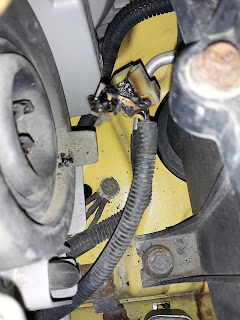
The first solution is to remove the three 4.7K resistors (marked 472 in the picture) and replace them with external 4.7K resistors to 3.3 or even 5 volts.  The second solution is to cut the run connecting them to 1.8 volts and jumper them over to the 3.3 volt regulator.  The run to cut is marked in yellow in the following picture and then add the jumper marked in red.


This is a simplified schematic of the circuit board. Basically there are two voltage regulators.


Once that change is made the MAX30100 works great.  The "Minimum" example gives beat detection, BPM and SPO2 to the Arduino serial monitor.  Just add a little code and redirect it to a LCD and this is what you get.

However the MAX30102 requires a different library and I could not find one nearly as good as the library for the MAX30100.  Someone has commented that not only is the device ID different (15 instead of 11) but the register addresses are also different.  Well, not only that, but the register for the LED's changes to one register (4 bits per LED) to two registers (8 bits per LED)! 

I decided to fork the MAX30100 library and make it into a MAX30102 library.  It is not nearly as easy as changing the register numbers!  Here is what I have done so far:
1. Copy all src files and rename them as MAX20102_XXXX
2. Edit all src files contents to replace MAX30100 wit MAX30102
3. Change device ID from 11 to 15
4. Change registers as follows:
    A. 01->02
    B 02->04
    C 03->05
    D 04->06
    E 05->07
    F 06->09
    G 07->0A
    H 09->0C and 0D
    I 16->1F
    J 17->20
5. Create second LED2_PA register (addx 0D above)
6. Biggest issue:  MAX30100 has 16 bit analog converters fitting into 2 byte transfers.
                            MAX30102 has 18 bit analog converters fitting into 3 byte transfers!
Here is the solution (I think) I wasted 2 bits of data but fit it into 16 bits:
             .ir=(uint16_t)((buffer[i*6]<<14)|(buffer[i*6+1]<<6)|buffer[i*6+2]>>2),
              .red=(uint16_t)((buffer[i*6+3]<<14)|(buffer[i*6+4]<<6)|buffer[i*6+5]>>2) });


Wednesday, February 10, 2021

I am working on an update to the 6DOF Servo Arm project

 I am updating the 6DOF Servo Arm project.  The old arm had some issues.  Like the servos at the wrist position jammed on each others limiting the range of motion.  Here is a picture of the old arm.


This is what the new arm looks like.  Note the spacer in the middle and how the last two servos are connected together.  This arrangement gives a much better range of motion.

First I need to improve the "Claw".  The clear plastic claw looks better if it is painted black.  But the plastic where it attaches keeps breaking, so I made an aluminum bracket to do the job.


Then I needed to improve the controller.  The servo or I/O shield for the Arduino has many issues that I have covered in another post.  I thought I would use the Nano Shield as the Nano has two more outputs that ne Uno.  Those being A6 and A7.  That way it can run 21 servos!  But the Nano shield could not even run six servos without smoke rolling out of it.  The problem is that the five volt power source on the shield uses the five volt regulator located on the Nano and it is woefully underpowered.  To fix it I cut the run to the 5V pin of the Nano (Circled in red in the picture below) and then jumpered the power input to the 5V terminal.  At first I had jumpered the VIN terminal to the 5V terminal, but then smoke rolled out of the diode that is between the input jack and the VIN pin to protect against reversing the power.  That diode also costs you about 1 volt of power to the servos and at four volts they do not work very well at all.


A video of the first successful test run is on YouTube: