// Sunrise 7x96 Uno LED Array driver
// Easier to read code
// 4/4/2024 by Bob Davis
#define Data 7// Data pin
#define CLK 8 // Port B assignments
#define OE 9 // 74138 pins 4 and 5
#define LAT 10// Latch
#define A0 11 // 74138 pin1
#define A1 12 // 74138 pin2
#define A2 13 // 74138 pin3
String text="ARDUINO+SUNRISE ";
// This font from http://sunge.awardspace.com/glcd-sd/node4.html
byte font[][7] = {
0x00,0x00,0x00,0x00,0x00,0x00,0x00, // ascii 32
0x00,0x00,0xfa,0x00,0x00,0x00,0x00, // !
0x00,0xe0,0x00,0xe0,0x00,0x00,0x00, // "
0x28,0xfe,0x28,0xfe,0x28,0x00,0x00, // #
0x00,0x34,0xfe,0x58,0x00,0x00,0x00, // $
0xc4,0xc8,0x10,0x26,0x46,0x00,0x00, // %
0x6c,0x92,0xaa,0x44,0x0a,0x00,0x00, // &
0x00,0xa0,0xc0,0x00,0x00,0x00,0x00, // '
0x00,0x38,0x44,0x82,0x00,0x00,0x00, // (
0x00,0x82,0x44,0x38,0x00,0x00,0x00, // )
0x10,0x54,0x38,0x54,0x10,0x00,0x00, // *
0x10,0x10,0x7c,0x10,0x10,0x00,0x00, // +
0x00,0x0a,0x0c,0x00,0x00,0x00,0x00, // ,
0x10,0x10,0x10,0x10,0x10,0x00,0x00, // -
0x00,0x06,0x06,0x00,0x00,0x00,0x00, // .
0x04,0x08,0x10,0x20,0x40,0x00,0x00, // /
0x7c,0x8a,0x92,0xa2,0x7c,0x00,0x00, // 0
0x00,0x42,0xfe,0x02,0x00,0x00,0x00, // 1
0x42,0x86,0x8a,0x92,0x62,0x00,0x00, // 2
0x84,0x82,0xa2,0xd2,0x8c,0x00,0x00, // 3
0x18,0x28,0x48,0xfe,0x08,0x00,0x00, // 4
0xe4,0xa2,0xa2,0xa2,0x9c,0x00,0x00, // 5
0x3c,0x52,0x92,0x92,0x0c,0x00,0x00, // 6
0x80,0x8e,0x90,0xa0,0xc0,0x00,0x00, // 7
0x6c,0x92,0x92,0x92,0x6c,0x00,0x00, // 8
0x60,0x92,0x92,0x94,0x78,0x00,0x00, // 9
0x00,0x6c,0x6c,0x00,0x00,0x00,0x00, // :
0x00,0x6a,0x6c,0x00,0x00,0x00,0x00, // ;
0x00,0x10,0x28,0x44,0x82,0x00,0x00, // <
0x28,0x28,0x28,0x28,0x28,0x00,0x00, // =
0x82,0x44,0x28,0x10,0x00,0x00,0x00, // >
0x40,0x80,0x8a,0x90,0x60,0x00,0x00, // ?
0x4c,0x92,0x9e,0x82,0x7c,0x00,0x00, // @
0x7e,0x90,0x90,0x90,0x7e,0x00,0x00, // A
0xfe,0x92,0x92,0x92,0x6c,0x00,0x00, // B
0x7c,0x82,0x82,0x82,0x44,0x00,0x00, // C
0xfe,0x82,0x82,0x82,0x7c,0x00,0x00, // D
0xfe,0x92,0x92,0x92,0x82,0x00,0x00, // E
0xfe,0x90,0x90,0x80,0x80,0x00,0x00, // F
0x7c,0x82,0x82,0x8a,0x4c,0x00,0x00, // G
0xfe,0x10,0x10,0x10,0xfe,0x00,0x00, // H
0x00,0x82,0xfe,0x82,0x00,0x00,0x00, // I
0x04,0x02,0x82,0xfc,0x80,0x00,0x00, // J
0xfe,0x10,0x28,0x44,0x82,0x00,0x00, // K
0xfe,0x02,0x02,0x02,0x02,0x00,0x00, // L
0xfe,0x40,0x20,0x40,0xfe,0x00,0x00, // M
0xfe,0x20,0x10,0x08,0xfe,0x00,0x00, // N
0x7c,0x82,0x82,0x82,0x7c,0x00,0x00, // O
0xfe,0x90,0x90,0x90,0x60,0x00,0x00, // P
0x7c,0x82,0x8a,0x84,0x7a,0x00,0x00, // Q
0xfe,0x90,0x98,0x94,0x62,0x00,0x00, // R
0x62,0x92,0x92,0x92,0x8c,0x00,0x00, // S
0x80,0x80,0xfe,0x80,0x80,0x00,0x00, // T
0xfc,0x02,0x02,0x02,0xfc,0x00,0x00, // U
0xf8,0x04,0x02,0x04,0xf8,0x00,0x00, // V
0xfe,0x04,0x18,0x04,0xfe,0x00,0x00, // W
0xc6,0x28,0x10,0x28,0xc6,0x00,0x00, // X
0xc0,0x20,0x1e,0x20,0xc0,0x00,0x00, // Y
0x86,0x8a,0x92,0xa2,0xc2,0x00,0x00, // Z
};
void setup() {
Serial.begin(9600);
Serial.println("Arduino is ready");
pinMode (Data, OUTPUT); // Data pin to output
pinMode (CLK, OUTPUT); // Clock pin to output
pinMode (OE, OUTPUT); // Out Enable pin to output
pinMode (LAT, OUTPUT); // Latch pin to output
pinMode (A0, OUTPUT); // Address pin to output
pinMode (A1, OUTPUT); // Address pin to output
pinMode (A2, OUTPUT); // Address pin to output
}
void loop() {
if (Serial.available() > 0){
text=Serial.readString();
text.toUpperCase();
Serial.print(text);
}
// Select the Row
for (int r=0; r<8; r++){
// select the character
for (int ch=17; ch>-1; ch--){
// select the column within character
for (int c=5; c>-1; c--){
digitalWrite(Data, HIGH); // Data is inverted!
if ((font[text[ch]-32][c] >> r+1) & 0x01==1) digitalWrite(Data, LOW);
digitalWrite(CLK, LOW); // Toggle Clock
digitalWrite(CLK, HIGH);
}
}
// This row is done so display it
digitalWrite(OE, HIGH); // Turn off display
digitalWrite(LAT, HIGH); // Latch data
digitalWrite(LAT, LOW); // Ready for next latch
digitalWrite(A0, LOW); // Update Row
digitalWrite(A1, LOW);
digitalWrite(A2, LOW);
if ((r & 0X01)==1) digitalWrite(A0, HIGH);
if ((r & 0X02)==2) digitalWrite(A1, HIGH);
if (r > 3) digitalWrite(A2, HIGH);
digitalWrite(OE, LOW); // Display back on
}
}
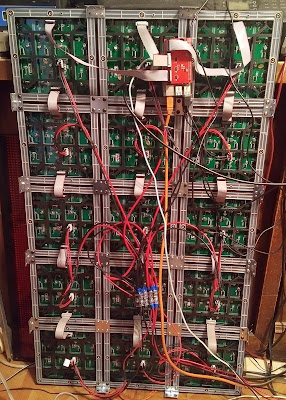
Here is a picture of the wiring from the back side.