Showing posts with label Robotics. Show all posts

Monday, February 23, 2026

Simpler Arms for InMoov Robot

I have built several humanoid servo based robots over the years as can be seen in this blog.  The InMoov Robot arms are very complicated to build so I have simplified them with standard servo parts enlarged 50% to work with the larger HS-805 servos. These parts can be found on thingiverse.

https://www.thingiverse.com/thing:7291737

The changes consist of servo mounting brackets and U arms that the servo rotates.


Her is one possibility for a arm made from these parts.


Thursday, February 5, 2026

Rebuilding my InMoov Robot Head

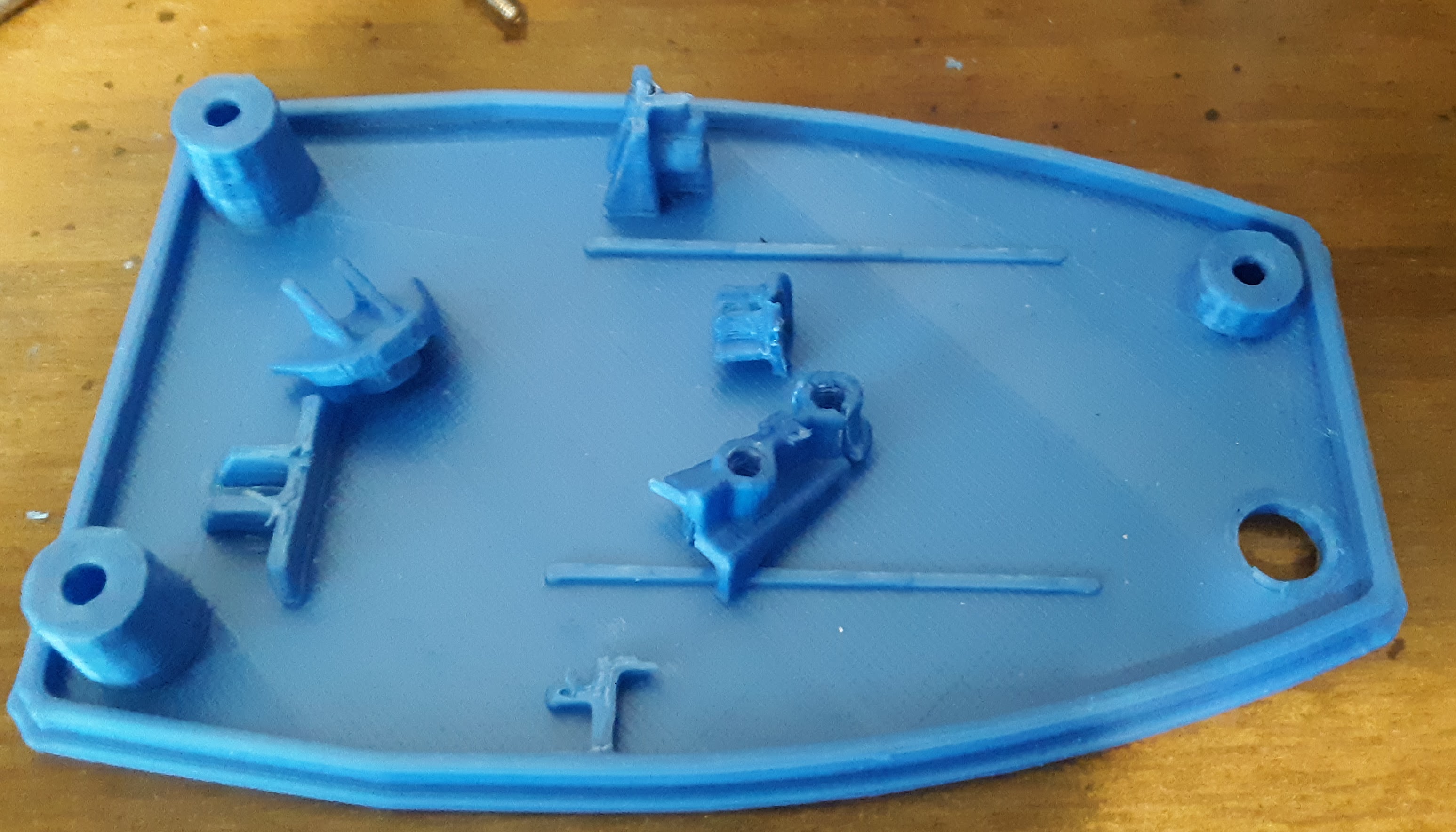
I am Rebuilding my InMoov Robot Head.  It was printed years ago on a plastic 3D printer.  I am now on my third metal framed 3D printer and the parts are coming out perfect.  So I replaced a lot of bad parts and rebuilt it. This picture shows some of the defective parts that needed replacement.


Here are some pictures of the rebuilt head. I am using a standard servo for the head rotation with a 3D printed adapter.  I developed an adapter plate that is found on thingiverse. https://www.thingiverse.com/thing:7288822


Friday, June 21, 2024

InMoov Compatible Hand Design Upgrade

I am working on a InMoov Compatible Hand Design Upgrade.  The main goal is to put all the servos in the hand.  Years ago I printed out a hand only to discover that all the servos are in the forearm.  Recently I though I could do better.  So far I am on my third hand.

This is what it looks like so far.  I used the one piece finger segments and printed them laying down with supports to plate only.  The servo arms will need to be two sided or 3D printed.


Onthe left are the first three attempts to print the improved hand.  In the latest version the servos are indented 6mm so they stick out the back side of the hand slightly.


Thursday, March 7, 2024

Rocker Bogey 6 Wheel Drive Mars Rover

 I had about eight wheels and matching motors around so I decided to make a six wheel drive Arduino controlled rover.  Then I discovered the rocker-bogie design that can handle really fough terrain.  So I 3D printed a design and modified it for a bigger platform for the electronics.

I have not figured out the front suspension yet and I would love to include one of my 3D prited Nerf guns in the design!


I cut a hold to mount a rotating servo in the middel of the platform.  there is not enough room for the arduino, batteries, and motor controller!


Friday, February 3, 2023

Battery powered Rapid Fire Rektify Nerf gun

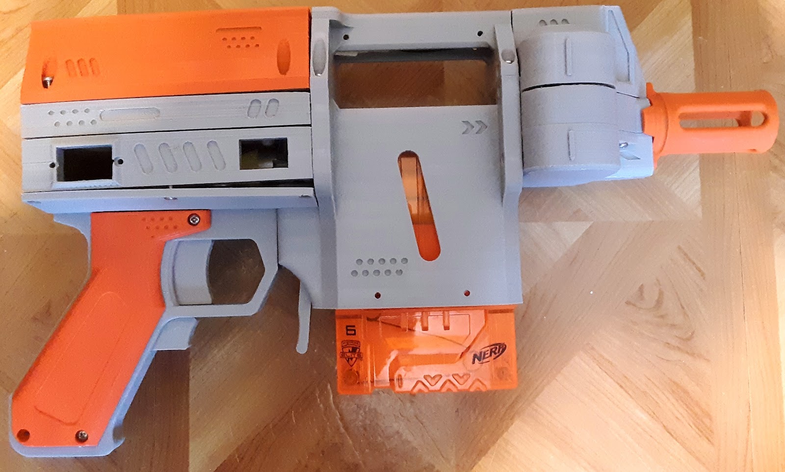
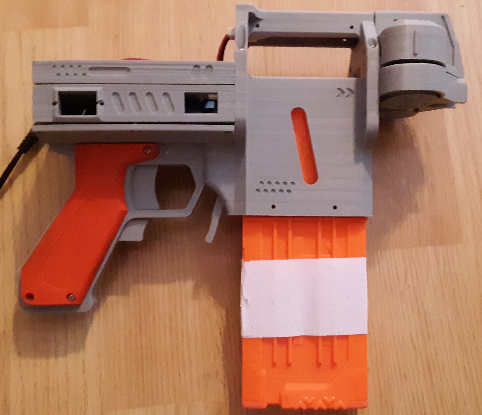
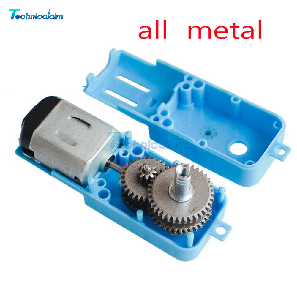
I 3D printed yet another nerf gun.  The design I used is called "rektify" and is located on thingiverse here: https://www.thingiverse.com/thing:3024361 However it needed some improvements.  The biggest problem is that the pusher would strip out the gears in the 90:1 motor gearbox.  Then I found an all metal gear version on ebay and that solved the problem.  Also I used washers as spacers between the layers around the pusher assembly.  Without the washers it gets stuck.  Another change was to drill out holes for the pusher motor gearbox mounting screws heads.  


I tested it with a 12 round magazine as well. The video is on youtube and facebook.

These are pictures of the all metal gears motor driver gearbox.


Wednesday, June 29, 2022

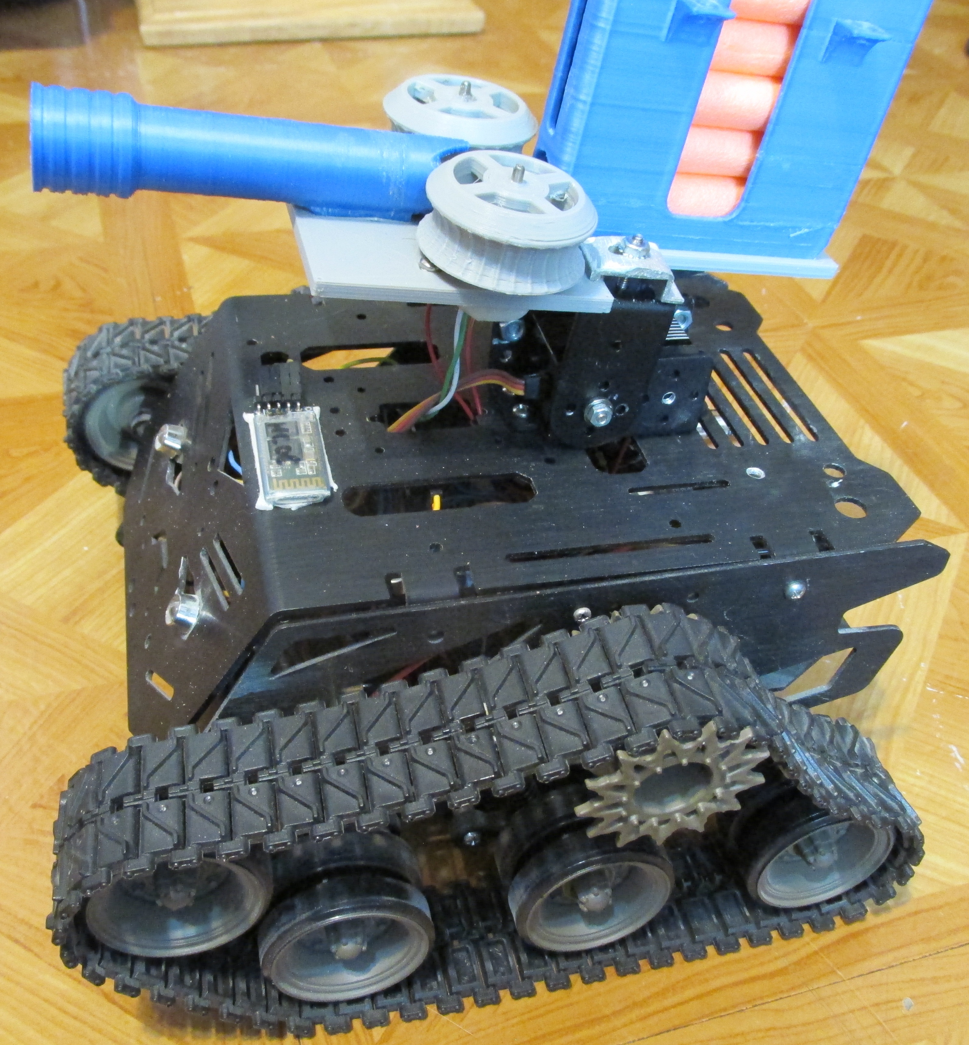
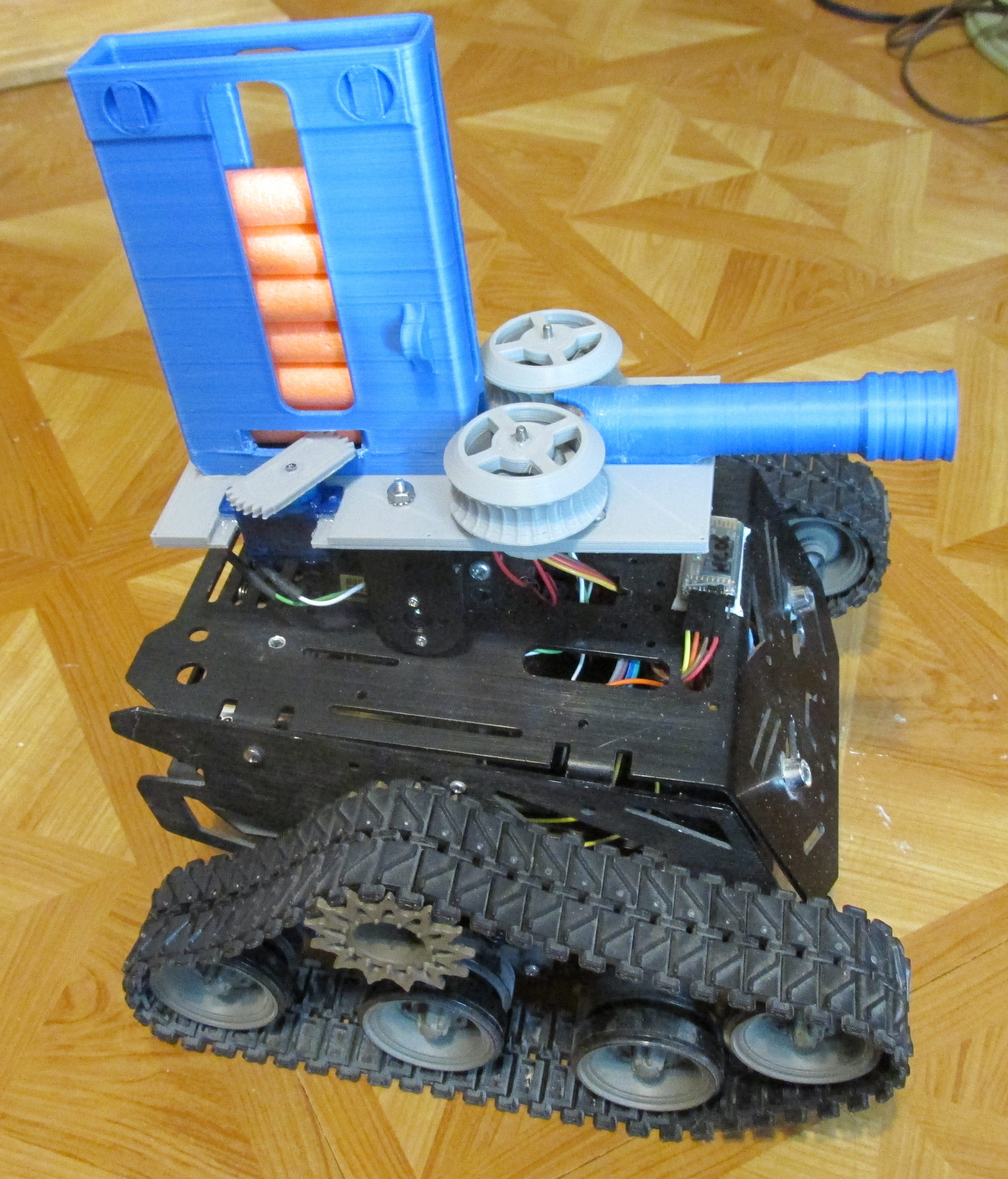
Arduino Tank with Nerf Launcher

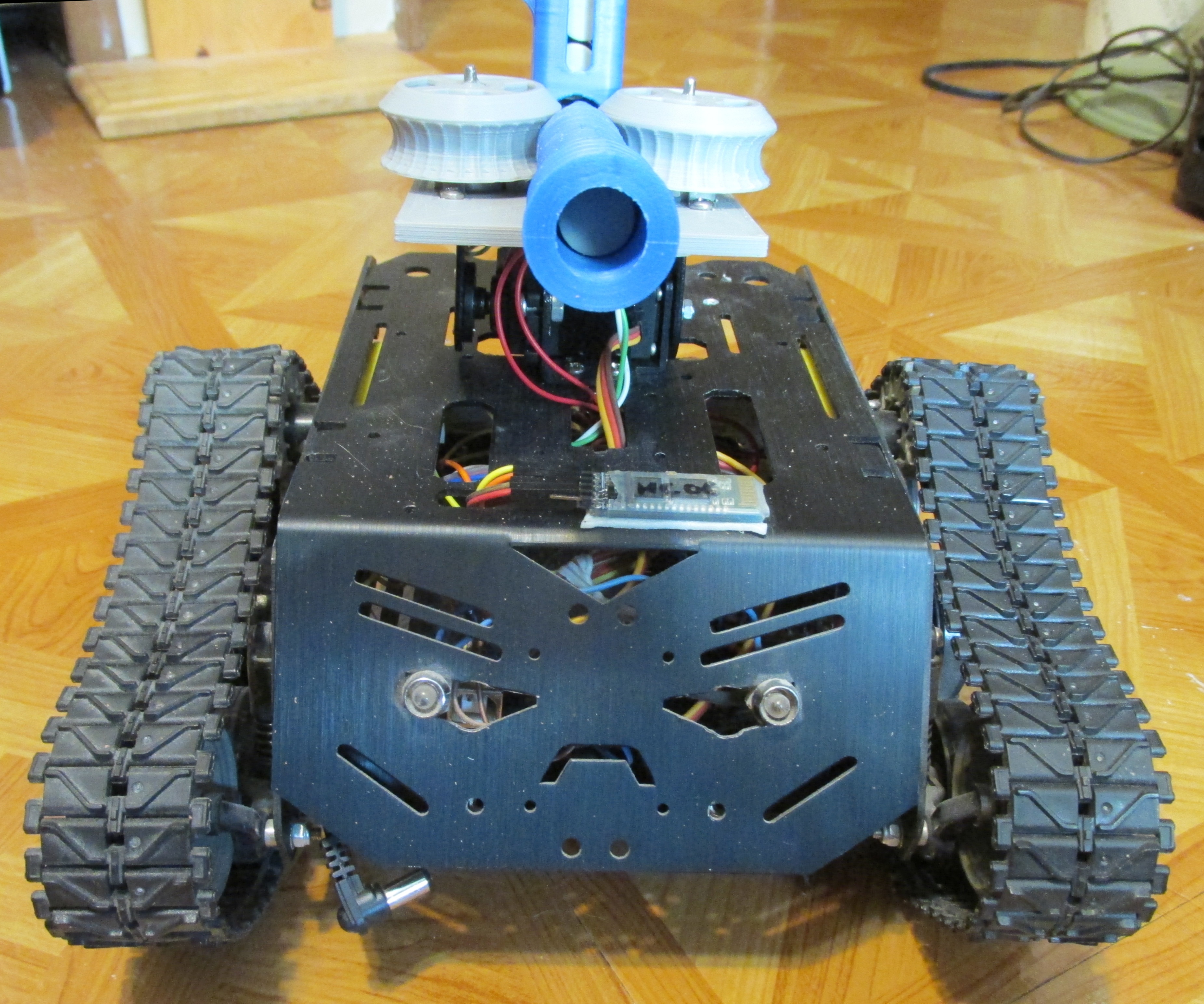
I added the 3D Printed Nerf Launcher to the Arduino controlled tank.  I can control it from my phone via Bluetooth control.  I used a standard servo to make the attachment.  This gives me up/down capability.


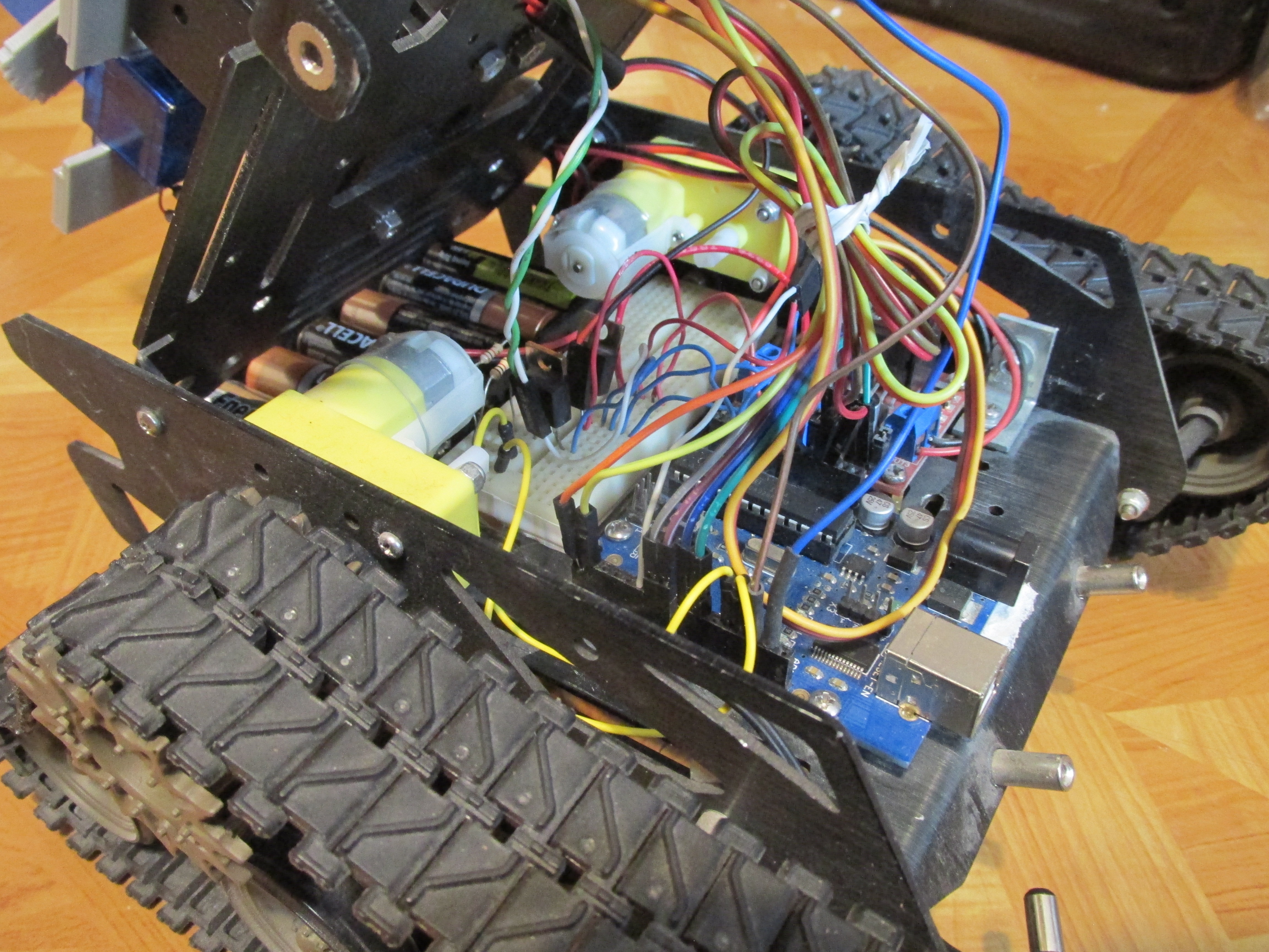
The interface uses 1K ohm resistors to TIP127 transistors to turn the motors on and off.  The small servo doing the pushing had its electronics removed and was modified for infinite 360 degree operation.
Here are some pictures of the insides of the tank.


Here is the YouTube video of the tank with Nerf launcher in operation

Friday, May 20, 2022

InMoov head Working with Arduino UNO

I am just finishing up building the InMoov Robot head.  First you must know that there are about four revisions for every part.  For instance I did the earlier version of the eyes first.  They had very limited range of motion.  So I made a newer version and they had much better movement.

I also tried painting the parts for the first time.  I used paint-able caulk first, then several layers of a sand-able undercoat followed by at least 2 layers of paint.  This next picture shows the results.

This is what it looked like before painting, the holes have been filled with caulk. I do not know why there are so many holes in the design!

This is what the eye assembly looked like.  I modified it slightly to fit an older Logitech webcam guts.  However the camera was upside down when it was tested.

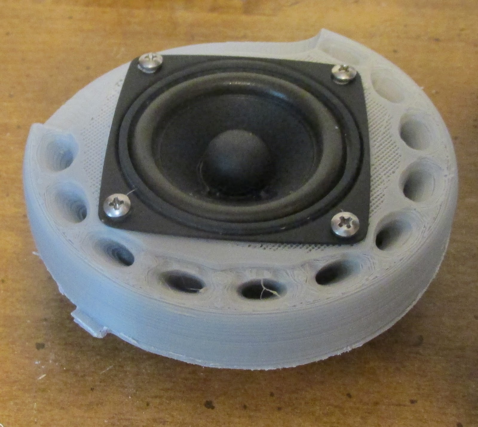
I modified the gear for the mouth and the ears as well.  I wanted ears that were fairly flat, but that resulted in the magnet hitting the jaw mechanism.  I will have to find some lower profile speakers.

I also located and added a base.  The real inMoov robot has more than just a head, but I wanted to stop there for now.  I had to cut the throat piston off at about one inch shorter to fit properly with the stand.

Here is what the completed robot head looked like.

I also recorded a video of me testing the servos to see if everything worked.  I used some MG958 servos that are twice as powerful as standard servos but I was not sure if they would be powerful enough.


Friday, April 15, 2022

EZ Robot JD Humanoid Painting and Repairs.

My third humanoid robot is working to some degree.  I have had lots of problems with the 3D printed parts.  The filament was likely the issue because I have used 2 other filaments that did not break as easily.  His feet kept beaking amoung other things.  I glued them back together several times.  Then I finally gave up and used metal servo brackets to fix his feet.

First I removed what was left of the broken parts leaving a smooth surface.


Next I mounted the metal bracket as shown in the picture below.  I should have used the other two outside holes as the bracket angles up slightly.  Note the use of a servo mounting spacer to make the screw a little longer.


Then the servo is mounted to the bracket as shown in the next picture.  Be sure to screw the servo center to the leg piece first, then screw the servo to the metal bracket.  His shoes do not fit over the metal bracket so it might need to be modified as far as the bracket height goes.


Another issue with the filament I was using is how bad it looks.  I printed the torso on its flat side so it took 30% less time and less filament.  However that left the surface looking a little rough.  I watched several videos and then decided to prime and paint it.  I used three layers of sandable primer with light sanding between them.  BTW I did the same thing with his shoes to save time and filament.  However the two cans of spray paint were nearly $20!!

This shows how bad the torso looked. It has been lightly sanded for this picture.


After three coats of primer with light sanding betwen them it already looks better.


Then the final product, it looks really good!  Issues included needing to fix any cracks before you start.  There were some cracks on the sides that are still visable.  You can use a soldering iron on the inside to carefully melt them back together.  I had previously reinforced some of the bottom with plastic pieces glued across the layers to hold them together.


Wednesday, March 30, 2022

Dual 80x160 RGB LCD Robot eyes

My latest creation uses dual 80x160 RGB LCD's to produce two robot eyes.  They are wired together so they can not "wink".  On the other hand it only takes half of the code.  They are powered by an Arduino UNO.  I was going to do this with OLED's but someone sent me a LCD instead so I went with the LCD's.  Theoretically you can wire them to have different "CS" or chip selects so each eye would be independent.  I added some more circles.  There is a small white circle on the far left and right as well as a black circle that produces the ring around the blue of the eyes.

By the way these LCD's are five volt friendly and easily run off five volts as well as use five volt logic levels.

Here are a couple of pictures.  They are more blue in reality but the camera has issues with the blue.


Here is a video of them on YouTube.


Ideally you could have two channels of your 32 channel servo controller go to analog inputs of an Arduino to set the size and direction of the eyes.

Here is the code:
// Sample program for eyes on 80x160 TFT LCD Screen
// March 2022 by Bob Davis

#include <TFT.h>  // Arduino LCD library
#include <SPI.h>
 
// Pins
#define cs   10
#define dc   8
#define rst  9
// For Arduino Uno: MOSI = pin 11 and SCLK = pin 13.  
// Create an instance of the library
TFT TFTscreen = TFT(cs, dc, rst);

int width=160; 
void setup() {
 
   // Initialize the screen
   TFTscreen.begin();
   // Clear the screen
   TFTscreen.background(255,255,255);
   // Set font color to white
   TFTscreen.stroke(255,255,255);
   // Set the font size
   TFTscreen.setTextSize(2);
   // Write some text on the screen
//   TFTscreen.text("Hello World!",0,0);
}
 
void loop() {
   TFTscreen.background(255,255,255); // Clear Screen

   // Eyes Center  NOTE SCREEN IS UPSIDE DOWN 0,0=bottom right
   TFTscreen.fillCircle(25,65,15,0x0000);
   TFTscreen.fillCircle(135,65,15,0x0000); 
   TFTscreen.fillCircle(45,65,30,0x0000);
   TFTscreen.fillCircle(115,65,30,0x0000); 
   TFTscreen.fillRect(45,35,70,61,0x0000); // Connect Circles
   TFTscreen.fillCircle(80,65,35,0xFFFF);
   TFTscreen.fillCircle(80,65,30,0xFFE0);
   TFTscreen.fillCircle(80,65,10,0xFFFF);
   delay(1000);

   // Eyes Narrow
   TFTscreen.fill(255,255,255);
   TFTscreen.rect(0,30,160,20);
   TFTscreen.rect(0,78,160,21);
   delay(1000);

   // Eyes Right
//   TFTscreen.background(255,255,255);
   TFTscreen.fillCircle(25,65,15,0x0000);
   TFTscreen.fillCircle(135,65,15,0x0000); 
   TFTscreen.fillCircle(45,65,30,0x0000);
   TFTscreen.fillCircle(115,65,30,0x0000); 
   TFTscreen.fillRect(45,35,70,61,0x0000);// Connect Circles
   TFTscreen.fillCircle(110,65,35,0xFFFF);
   TFTscreen.fillCircle(110,65,30,0xFFE0);
   TFTscreen.fillCircle(110,65,10,0xFFFF);
   delay(1000);
   
   // Eyes Left
//   TFTscreen.background(255,255,255);
   TFTscreen.fillCircle(25,65,15,0x0000);
   TFTscreen.fillCircle(135,65,15,0x0000); 
   TFTscreen.fillCircle(45,65,30,0x0000);
   TFTscreen.fillCircle(115,65,30,0x0000); 
   TFTscreen.fillRect(45,35,70,61,0x0000);// Connect Circles
   TFTscreen.fillCircle(50,65,35,0xFFFF);
   TFTscreen.fillCircle(50,65,30,0xFFE0); // Blue
   TFTscreen.fillCircle(50,65,10,0xFFFF);
   delay(1000);
    
   // Eyes Big
   TFTscreen.fillCircle(25,65,15,0x0000);
   TFTscreen.fillCircle(135,65,15,0x0000); 
   TFTscreen.fillCircle(45,65,30,0x0000);
   TFTscreen.fillCircle(115,65,30,0x0000); 
   TFTscreen.fillCircle(60,65,40,0x0000);
   TFTscreen.fillCircle(100,65,40,0x0000); 
   TFTscreen.fillRect(65,25,40,81,0x0000); // Connect Circles
   TFTscreen.fillCircle(80,65,35,0xFFFF);
   TFTscreen.fillCircle(80,65,30,0xFFE0);
   TFTscreen.fillCircle(80,65,10,0xFFFF);
   delay(2000);
}

Monday, March 21, 2022

Nokia 5110 Robot Face Eyes and Mouth

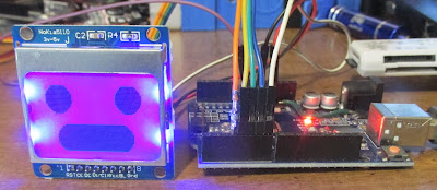
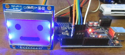
 I thought I would try using a Nokia LCD for creating a face for my robot.  However I was greatly disappointed.  If you make his eyes white, then the border is also white.  So I had to make his eyes black.  The effect is not nearly as pronounced.  As a result I only created two expressions for this LCD.

Here is the two faces:


Here is the code for those two faces.

/*********************************************************************
Nokia 5110 LCD Robot Face
Many thankls to AdaFruit!
*********************************************************************/
#include <Adafruit_GFX.h>
#include <Adafruit_PCD8544.h>
// Software SPI (slower updates, more flexible pin options):
// pin 7 21- Serial clock out (SCLK)
// pin 6 20- Serial data out (DIN)
// pin 5 19- Data/Command select (D/C)
// pin 4 18- LCD chip select (CS)
// pin 3 17- LCD reset (RST)
//Adafruit_PCD8544 display = Adafruit_PCD8544(21, 20, 19, 18, 17);
Adafruit_PCD8544 display = Adafruit_PCD8544(7, 6, 5, 4, 3);
void setup()   {
  display.begin();
  display.setContrast(60);  // Default is 50
  display.clearDisplay();   // clears the screen and buffer
}
void loop() {
  // draw big eyes and mouth
  display.fillCircle(display.width()/6, display.height()/5, 10, BLACK);
  display.fillCircle(display.width()/6*5, display.height()/5, 10, BLACK);
  display.fillCircle(display.width()/4, display.height()-10, 10, BLACK);
  display.fillCircle(display.width()/4*3, display.height()-10, 10, BLACK);
  display.fillRect(display.width()/4, display.height()-20,display.width()/4*2,20, BLACK);
  display.display();
  delay(2000);
  display.clearDisplay();
  // draw eyes and mouth
  display.fillCircle(display.width()/6, display.height()/5, 7, BLACK);
  display.fillCircle(display.width()/6*5, display.height()/5, 7, BLACK);
  display.fillCircle(display.width()/4, display.height()-10, 5, BLACK);
  display.fillCircle(display.width()/4*3, display.height()-10, 5, BLACK);
  display.fillRect(display.width()/4, display.height()-14,display.width()/4*2,10,BLACK);
  display.display();
  delay(2000);
  display.clearDisplay();
}

Monday, March 7, 2022

I am Making my Third Humanoid Robot

I have started on making my third humanoid robot.  This one is modeled after the EZ-Robot JD Humanoid.  The issue with the larger humanoids is that their center of gravity is way too high.  There is a two degree tolerance in each servo and that is amplified by the distance from the servo's.  So in a humanoid that is over 16" tall the two degrees can amount to falling over frontwards or falling over backwards.  That makes it really hard to write software for walking.  

One solution is to make the robot shorter and to make the distance from each servo shorter.  In the following picture there is a servo for the EZ_Robot on the left, for the Hadron Robot in the middle, and for the mechanical robot sold on eBay on hte right.  The EZ-Robot assembly is so short that the ears need to be cut off the one end of the servo for it to work.  The Hadron robot on the other hand is not much smaller than the mechanical version, it also is not quite square.


As I tried more options the possibilities expanded to five different versions.  I think I will have to design my own!


The robot body would take 16 hours to print as designed.  I turned it over and that reduced the time to 10 hours.  However since there would be supports under the front, the front surface is not a smooth.  
Then I ran into the issue with the shoulder servos needing their tabs cut off.  What is it with the designers and cutting the mounting tabs off the servos??


My solution was to cut some slots in the top for the servo mounting tabs.  I used a soldering iron to do that trick.  BTW when I added the legs the body broke in half!  These parts fit way too tight.  I file them off so they are smooth before even trying to fit them together.

The robot is now about 1/2 way completed.  Here is what he looks like so far.

The next issue was that the shoulders (Servo horn extenders) keep breaking in half.  So I rotated them so they stand up before printing them and that seems to fix the issue.


The U brackets for the legs kept breaking.  So I developed my own design.  

So far I have come up with six different servo U bracket design options.  The five on the left do not require you to cut off the servo mounting tabs and they do not break as easily as the ones normally used for this robot.  Somehow I lost the mounting holes in the fifth one but I added them back in later on.


So far he is coming together. The head has too big of an opening for the LCD screen.  I cut it for a 2.5" LCD but then the screen did not fit because the LCD circuit board was too big.  I may have to make a bezel for the LCD to cover the mistakes.....

I almost gave up on his hands.  I have piles of servos but none are the size that properly fit his hands.  There is a size of servo that is in between the SG90/HS55 and the normal sized servo (They are marked "PKZ1060") but even they do not fit.  So I modified the hands to use the SG90 sized servos.  I had to drill out the servo end so the white servo arm would fit through it then I melted a hole for the screw that locks the arm to the printed arm.


I had to remove the left side (It broke off anyway) and then trim a little for the round part of the servo to fit.  Then I used lots of glue to hold the servo in place.  I had trouble with mounting the hands to the arms so I added a screw, as can be seen below the servo in this picture.


Here is what he looks like with his hands attached.  Now to add a servo controller.


This next picture is a size comparison.  JD Humanoid is in the front left.  To the right is the Robosoul HS3 and behind them is the humanoid that is sold on eBay.