Monday, July 27, 2015

2.2 or 2.4 or 2.8 inch SPI TFT LCD ILI9341 to Arduino Uno

Over the weekend I figured out how to interface a 2.8 inch SPI TFT that has a ILI9341 chip to an Arduino Uno.  All it takes is eight 1K resistors.  Most people use a 4050 IC.  Here is the schematic.

I am using the Adafruit ILI9341 driver found at: https://github.com/adafruit/Adafruit_ILI9341
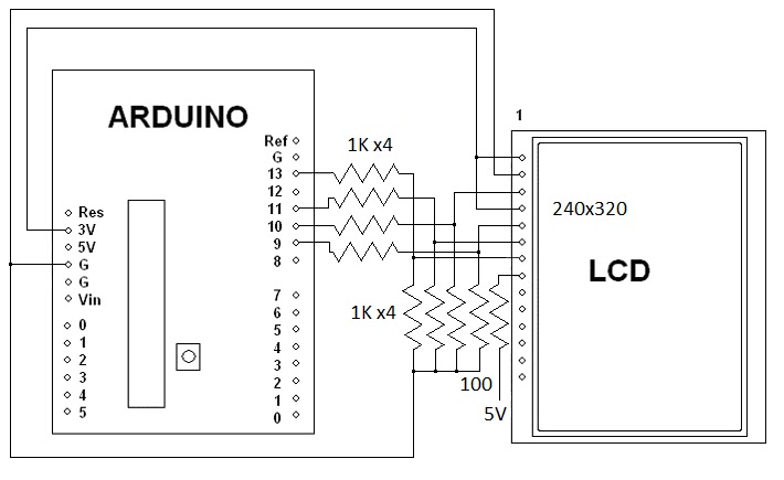
Note that the Adafruit LCD has level shifters for 5 volts built into it.

Here is a video of it working on Youtube.

Here is a video of the LCD being used as an oscilloscope.


Here are a couple of still pictures, only 6 of the 8 bits are connected for these pictures.


Here is the code for a more basic oscilloscope.

/************************************
 2.8 SPI PIND TFT Oscope Simple
 Reads the D0-D7 pins using PIND,
 and shows the value on the screen.
 Created 27 july 2015 by Bob Davis
**************************************/
//#include  // Arduino LCD library
#include
#include "Adafruit_ILI9341.h"
#include "Adafruit_GFX.h"

// pin definition for the Uno LCD
#define TFT_DC 9
#define TFT_CS 10
// Use hardware SPI (on Uno, #13=clk, #11=mosi) and the above for CS/DC
//Adafruit_ILI9341 tft = Adafruit_ILI9341(TFT_CS, TFT_DC);
Adafruit_ILI9341 tft = Adafruit_ILI9341();

//// set up variables
int Input=0;
byte Sample[320];
int trigger=64;

void setup(){
  // initialize rotate and clear the display
  tft.begin();
  tft.fillScreen(ILI9341_BLACK);
  tft.setRotation(1);
  // Set the font size
  tft.setTextSize(2);
  // D input pins
  pinMode(0, INPUT);
  pinMode(1, INPUT);
  pinMode(2, INPUT);
  pinMode(3, INPUT);
  pinMode(4, INPUT);
  pinMode(5, INPUT);
  pinMode(6, INPUT);
  pinMode(7, INPUT);
}

void loop(){
  // wait for a positive going trigger
  for (int timeout=0; timeout < 1000; timeout++){
    Input = PIND;
    if (Input < trigger) break;  }
  for (int timeout=0; timeout < 1000; timeout++){
    Input = PIND;
    if (Input > trigger) break;  }
  // quickly collect the data with no delay
  for (int xpos=0; xpos <320; xpos++){
  Sample[xpos]=PIND;
  // display the collected data
  for (int xpos=0; xpos <319; xpos++){
  // erase the old and draw new line
    tft.drawLine(xpos+1, 0, xpos+1, 240, ILI9341_BLACK);
    tft.drawLine(xpos, (Sample[xpos]*2), xpos+1, Sample[xpos+1]*2, ILI9341_WHITE);
  }
}
// End of program

There is more info on the analog to digital converter at http://bobdavis321.blogspot.com/2015/06/arduino-5msps-oscilloscope-revisited.html

Sunday, July 19, 2015

2015 Batavia NY Hamfest

This year I made it back to the Batavia NY Hamfest!   It was bigger than most of the Hamfests that I make it to.  The picture only shows one of two isles of equipment for sale.  I forgot my camera and it was dark so my cell phone pictures are not that great, sorry about that.

Here is my stuff for sale.  The car does not fit as much stuff as the van did.

Thursday, July 16, 2015

Walking "Humanoid" Robot found on eBay.

My book "Arduino Robotics Projects" ended with a walking dinosaur.  I might eventually write a sequel to that book with a spider and a humanoid robot.  One of those projects that I have been working on is a walking "Humanoid" robot.  Recently I completed building the legs.

Here are some of the many parts that comes with the robot found on ebay.

Here is the actual parts list:
- 16 x Multi-functional servo bracket
- 7 x Short U-type servo bracket
- 4 x Long U-type servo bracket
- 4 x Angled U-type servo bracket
- 4 x Flat servo bracket
- 4 x L-type servo bracket
- 1 x U-type robot waist bracket (not pictured, I made my own)
- 2 x Foot Base
- 14 x Miniature Ball Radial Bearing
- 17 x Metal Servo Horn Flange
- 1  x Screw and nut set

You will also need flanges, bearings and lots of screws.  Do not use the pictured 16 channel servo controller you will need a 32 channel servo controller.

You will also need about 17 servo motors!  Here is a few of them, they are MG995's.

Here is how to assemble the feet.  Use the flat head M4 screws as seen on the right side.


There are two ways to mount the bearing as seen on the left in the above picture.  You can put the screw in first and then bend the "U" metal bracket over the screw and bearing.  The other way is to use tweezers to hold the nut in place and then put the screw in as seen above.

When I started I used the wrong screws to hold the servo's in place.  You are supposed to use the M4 screws (A little bigger than a 6-32 screw) but I used the M3 screws (about the size of a 4-40 screw) instead.  I am in the process of changing all of the servo mounting screws.  Also my guess is that the four screws used to hold the servo flange to the "U" bracket are supposed to be flat head screws.  The rounded or pan head screws are for the center of the flange to fasten it to the servo.

I am making my own breast plate that looks better than one made out of small parts.  It is made out of a left over 4 inch piece of 3 inch "C" channel removed from a 19 inch rack.

Here is the completed and painted chest piece.

I have assembled the robot with the home made chest.  I used 1/2 inch spacers to move the shoulder servo's out to where the head mounting bracket fits between them.  Note that I only used 4 servo's per leg, I think that is all that is needed.


Thursday, July 2, 2015

Arduino 50 MSPS DSO Oscilloscope with TDA8703

Last night I was testing a TDA8703 analog to digital converter and after trying 36 MHz I tried 50 MHz on a whim and it worked.  I also tried 60 MHz but the TDA8703 flaked off at that speed.

Here is a picture of the test setup.

This is what the LCD screen looks like.

Here is the video of it at 50 MSPS and 25MSPS.


Here is the schematic diagram.