I am finishing up the biggest project for my latest book on LED cubes. Here are a couple of video's about the 8x8x8 color LED cube.
In this first video it was just 7x7x2 in size:
In this next video it is up to 7x7x4 in size and still growing as more LED's arrive:
It has now grown to 8x8x4 in size.
I will have to use a pad per hole soldered breadboard to proceed any further. The 7x7x4 setup takes over 200 jumpers to connect everything. I would buy a printed circuit board but as far as I know no one makes one that meets my standards! The closest design I have found uses latches and lots of transistors and resistors. My design uses nothing but 74HC595 shift registers and a ULN2803.
Here are the red, green, blue and white test pictures.
And now the schematic for one layer...
Someone pointed out that the resistor values are not given in the schematic above. You can use from 47 to 100 ohms, I was using 51 ohm resistors.
I was at a yard sale and I asked them about a 32 inch TV. They said it was free because the screen did not light up. It turned out to be the same model and have the same problem that I have diagnosed before. It was bad capacitors in the HV power supply for the backlight.
Here is a picture of the bad 10 uF at 450 volt capacitors.
I replace them with 2 or 4 uF at 400 volt paper capacitors. There is a hole pattern already there for the larger capacitors. This picture shows the old holes and the new holes to use.
Here is what the new capacitors look like installed on the High Voltage power supply.
I completed the third application for my 8x8x8 LED cube. First it was to use it with an Arduino, then with a Raspberry Pi and then this kit that I bought on eBay. At first I thought it was not working because it is so dim that you have to turn down the lights to watch it. Once that problem was fixed I then reverse engineered it to work with an Arduino once again.
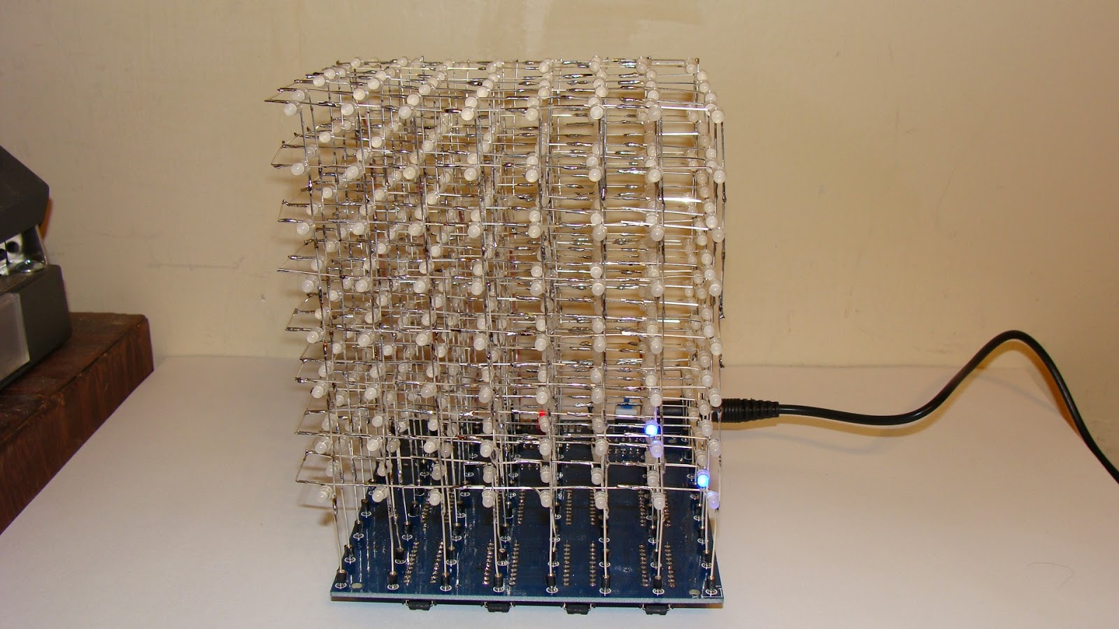
Here is the front view of the completed 8x8x8 LED cube kit.
This is the back view. You can see the wires going up to the eight layers.
Here is the bottom view so you can see the IC's.
This it the video of it on YouTube.
The design problem is that there should be a resistor in each LED leg, that would take 64 resistors. Instead they used 8 resistors in the common cathode circuit. As a result the brightness of each layer varies depending upon how many LED's are lit up. The more led's are lit the dimmer the layer becomes. I might try to fix this by adding a resistor on each of the 64 legs and removing the ones on the common cathode connection to each layer. If nothing else reducing the 500 ohm resistor to 100 or 220 ohms might do the trick.
Here is the quick fix - just change the 510 ohm resistors to 51 ohms. Then the display is much brighter. It is still not as bright as when I used 74595 shift registers.
I am now reverse engineering this LED cube to allow an Arduino to control it.
Here is the completed modification. It requires adding a 74LS138 IC. The latches need to be changed to 74HC574's to make it work properly with an Arduino.
This is the schematic diagram.
Here is a video of the cube kit working with the Arduino Uno.
Once it was interfaced to the Arduino I used a spare analog pin to add sound to it.