Friday, November 29, 2024

Sunrise Systems LED Sign revisited

 I was asked to convert another Sunrise Systems LED sign to Arduino control and wireless updates via bluetooth.  This time I wanted to make the conversion simpler by reusing the driver IC's and Transistors.  To do that I cut the board in half just to the right of the processor.  Then I tapped into signals on the 74HC04 and 74HC138.  The following picture shows the location for the cut and where to tap into the signals:

Here is a picture of the prototypeing of this new setup.  Everything worked but some of the signals were inverted so it took some playing with the code to get it to work.


I spliced in a bare board to add the arduino processor. 


Here is the revised code for a basic version of this arrangement;

// Sunrise 7x96 Uno LED Array driver
// Easier to read code
// 4/4/2024 by Bob Davis

#define Data 7// Data pin
#define CLK 8 // Port B assignments 
#define OE  9 // 74138 pins 4 and 5
#define LAT 10// Latch
#define A0 11 // 74138 pin1
#define A1 12 // 74138 pin2
#define A2 13 // 74138 pin3

String text="ARDUINO+SUNRISE  ";

// This font from http://sunge.awardspace.com/glcd-sd/node4.html
byte font[][7] = {
0x00,0x00,0x00,0x00,0x00,0x00,0x00, // ascii 32
0x00,0x00,0xfa,0x00,0x00,0x00,0x00, // !
0x00,0xe0,0x00,0xe0,0x00,0x00,0x00, // "
0x28,0xfe,0x28,0xfe,0x28,0x00,0x00, // #
0x00,0x34,0xfe,0x58,0x00,0x00,0x00, // $
0xc4,0xc8,0x10,0x26,0x46,0x00,0x00, // %
0x6c,0x92,0xaa,0x44,0x0a,0x00,0x00, // &
0x00,0xa0,0xc0,0x00,0x00,0x00,0x00, // '
0x00,0x38,0x44,0x82,0x00,0x00,0x00, // (
0x00,0x82,0x44,0x38,0x00,0x00,0x00, // )
0x10,0x54,0x38,0x54,0x10,0x00,0x00, // *
0x10,0x10,0x7c,0x10,0x10,0x00,0x00, // +
0x00,0x0a,0x0c,0x00,0x00,0x00,0x00, // ,
0x10,0x10,0x10,0x10,0x10,0x00,0x00, // -
0x00,0x06,0x06,0x00,0x00,0x00,0x00, // .
0x04,0x08,0x10,0x20,0x40,0x00,0x00, // /
0x7c,0x8a,0x92,0xa2,0x7c,0x00,0x00, // 0
0x00,0x42,0xfe,0x02,0x00,0x00,0x00, // 1
0x42,0x86,0x8a,0x92,0x62,0x00,0x00, // 2
0x84,0x82,0xa2,0xd2,0x8c,0x00,0x00, // 3
0x18,0x28,0x48,0xfe,0x08,0x00,0x00, // 4
0xe4,0xa2,0xa2,0xa2,0x9c,0x00,0x00, // 5
0x3c,0x52,0x92,0x92,0x0c,0x00,0x00, // 6
0x80,0x8e,0x90,0xa0,0xc0,0x00,0x00, // 7
0x6c,0x92,0x92,0x92,0x6c,0x00,0x00, // 8
0x60,0x92,0x92,0x94,0x78,0x00,0x00, // 9
0x00,0x6c,0x6c,0x00,0x00,0x00,0x00, // :
0x00,0x6a,0x6c,0x00,0x00,0x00,0x00, // ;
0x00,0x10,0x28,0x44,0x82,0x00,0x00, // <
0x28,0x28,0x28,0x28,0x28,0x00,0x00, // =
0x82,0x44,0x28,0x10,0x00,0x00,0x00, // >
0x40,0x80,0x8a,0x90,0x60,0x00,0x00, // ?
0x4c,0x92,0x9e,0x82,0x7c,0x00,0x00, // @
0x7e,0x90,0x90,0x90,0x7e,0x00,0x00, // A
0xfe,0x92,0x92,0x92,0x6c,0x00,0x00, // B
0x7c,0x82,0x82,0x82,0x44,0x00,0x00, // C
0xfe,0x82,0x82,0x82,0x7c,0x00,0x00, // D
0xfe,0x92,0x92,0x92,0x82,0x00,0x00, // E
0xfe,0x90,0x90,0x80,0x80,0x00,0x00, // F
0x7c,0x82,0x82,0x8a,0x4c,0x00,0x00, // G
0xfe,0x10,0x10,0x10,0xfe,0x00,0x00, // H
0x00,0x82,0xfe,0x82,0x00,0x00,0x00, // I
0x04,0x02,0x82,0xfc,0x80,0x00,0x00, // J
0xfe,0x10,0x28,0x44,0x82,0x00,0x00, // K
0xfe,0x02,0x02,0x02,0x02,0x00,0x00, // L
0xfe,0x40,0x20,0x40,0xfe,0x00,0x00, // M
0xfe,0x20,0x10,0x08,0xfe,0x00,0x00, // N
0x7c,0x82,0x82,0x82,0x7c,0x00,0x00, // O
0xfe,0x90,0x90,0x90,0x60,0x00,0x00, // P
0x7c,0x82,0x8a,0x84,0x7a,0x00,0x00, // Q
0xfe,0x90,0x98,0x94,0x62,0x00,0x00, // R
0x62,0x92,0x92,0x92,0x8c,0x00,0x00, // S
0x80,0x80,0xfe,0x80,0x80,0x00,0x00, // T
0xfc,0x02,0x02,0x02,0xfc,0x00,0x00, // U
0xf8,0x04,0x02,0x04,0xf8,0x00,0x00, // V
0xfe,0x04,0x18,0x04,0xfe,0x00,0x00, // W
0xc6,0x28,0x10,0x28,0xc6,0x00,0x00, // X
0xc0,0x20,0x1e,0x20,0xc0,0x00,0x00, // Y
0x86,0x8a,0x92,0xa2,0xc2,0x00,0x00, // Z
};

void setup() {
  Serial.begin(9600);
  Serial.println("Arduino is ready");
  pinMode (Data, OUTPUT); // Data pin to output
  pinMode (CLK, OUTPUT);  // Clock pin to output
  pinMode (OE, OUTPUT);   // Out Enable pin to output
  pinMode (LAT, OUTPUT);  // Latch pin to output
  pinMode (A0, OUTPUT);   // Address pin to output
  pinMode (A1, OUTPUT);   // Address pin to output
  pinMode (A2, OUTPUT);   // Address pin to output
}
     
void loop() {
    if (Serial.available() > 0){
      text=Serial.readString();
      text.toUpperCase();
      Serial.print(text);
      }
    // Select the Row
    for (int r=0; r<8; r++){
      // select the character
      for (int ch=17; ch>-1; ch--){
        // select the column within character
        for (int c=5; c>-1; c--){
          digitalWrite(Data, HIGH); // Data is inverted!
          if ((font[text[ch]-32][c] >> r+1) & 0x01==1) digitalWrite(Data, LOW);
          digitalWrite(CLK, LOW);  // Toggle Clock
          digitalWrite(CLK, HIGH);
        }
      }
      // This row is done so display it
      digitalWrite(OE, HIGH);  // Turn off display
      digitalWrite(LAT, HIGH); // Latch  data
      digitalWrite(LAT, LOW); // Ready for next latch
      digitalWrite(A0, LOW);  // Update Row 
      digitalWrite(A1, LOW);
      digitalWrite(A2, LOW);
      if ((r & 0X01)==1) digitalWrite(A0, HIGH);
      if ((r & 0X02)==2) digitalWrite(A1, HIGH);
      if (r > 3) digitalWrite(A2, HIGH);
      digitalWrite(OE, LOW);  // Display back on
      }
    }

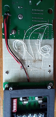
Here is a picture of the wiring from the back side.


Friday, June 21, 2024

InMoov Compatible Hand Design Upgrade

I am working on a InMoov Compatible Hand Design Upgrade.  The main goal is to put all the servos in the hand.  Years ago I printed out a hand only to discover that all the servos are in the forearm.  Recently I though I could do better.  So far I am on my third hand.

This is what it looks like so far.  I used the one piece finger segments and printed them laying down with supports to plate only.  The servo arms will need to be two sided or 3D printed.


Onthe left are the first three attempts to print the improved hand.  In the latest version the servos are indented 6mm so they stick out the back side of the hand slightly.


Wednesday, June 5, 2024

Converting TV to LED sign with 16x16 Arrays and SP801E

 I have been Converting an  old TV into a LED sign with 16x16 Arrays and SP801E controller.  At first I had 8 of the 16x15 ws2812 LED arrays then I added two of the 8x32 LED arrays to better fill in the screen area.

Here are two demo pictures.  One is a built in pattern and the other is a picture of my wifes pineapple upside down cake.


This is a close up picture of the controller.  I am only using 3 of the 4 outputs of the SP801E.  Each output can light up to 1024 LED's.


The screen is still not completely covered with the LED arrays.  But I do not know how to fill inthe last couple of inches of screen area.

Here is the latest video of the LED sign.

Friday, May 31, 2024

Repair of Suzuki GP-3 Digital Piano

My brother dropped off a Suzuki GP-3 electric digital piano for repairs. Many of the keys were stuck in the down position.  So I googled how to fix it and here is what I found:

Here is a video telling how to take it apart:

https://www.youtube.com/watch?v=KE7A7I0mirg

Then I found this coment on how to fix it at: 

https://www.yamaha-keyboard-guide.com/suzuki-keyboard-repair.html

"I used the orange fibreglass driveway marker from Home Depot. It’s the perfect size. With a rubber mallet I used it to punch out the old rods and replace them at the same time."

The first step was to remove the keys from the piano.


Then I tried to remove some of the individual keys. BTW you do not need to number the keys they are already numbered in the indentation area.  

Eventually I decided to remove every other octave, then remove all of the rods, then carefully push an orange driveway marker through all of the octaves.  I left the angled tip on the rod, and still had to lift some keys slightly to get the rod to go through them.  The commentator above said that he drove the marker through pushing the rods out as he went, but my keyboard was so far gone that that was not a possibility.  I had to use some pliers to twist and pull out the rods, one at a time, as they were really stuck in place.


When I put it back together there were way too many screws left over.  So I took it back apart and put in a lot of missing screws.  Even so I still had about 16 screws left over!!  

Thursday, March 7, 2024

Rocker Bogey 6 Wheel Drive Mars Rover

 I had about eight wheels and matching motors around so I decided to make a six wheel drive Arduino controlled rover.  Then I discovered the rocker-bogie design that can handle really fough terrain.  So I 3D printed a design and modified it for a bigger platform for the electronics.

I have not figured out the front suspension yet and I would love to include one of my 3D prited Nerf guns in the design!


I cut a hold to mount a rotating servo in the middel of the platform.  there is not enough room for the arduino, batteries, and motor controller!


Wednesday, February 21, 2024

Peavey Combo 115 repairs

My brother bought me a Peaver Combo 115 for repair.  They used controls with plastic shafts that broke off. They upgraded the design to use controls with metal shafts but they are out of stock everywhere unless you want to pay a fortune for them.

Here is a picture of the controls with their values and part numbers next to them.  You can see the broken controls in the picture.


This shows what the insides of the amplifier looks like. All of this could be 1/4 the size if it was made today.

The only critical controls that were broken were the 50K linear tone controls. The crossover and compressor can be ignored or bypassed.

Here is a possible source of parts.  The needed parts will cost you over $50 with shipping and may not be in stock.


As a solution I purchased 10 x 50K pots with knobs on eBay.  Short wires have to be run from each control to the circuit board.  I have seen this kind of solution before.


Wednesday, February 7, 2024

WARNING - 5630 LED strip lights are burning out!

I have many 5630 LED strip lights that have burned out after only 2 months of use.  Here is what they look like now that they have been replaced:


I used these LED strips to replace the five foot flouresent light bulbs in a street sign.  Here are the bad LED's as they were starting to burn up.  By the time I replaced them many more had burned out.


Monday, February 5, 2024

Arduino Powered Colloidal Silver Maker with Nokia 5110

I saw that someone had copied my colloidal silver maker design and their design was trending at number one when you search for Arduino Colloidal Silver Maker.  So I thought I would improve my previous design to use a Nokia 5110 LCD in the design instead of the 1602 LCD.  This Nokia display gives five or six lines of display so you can see more information.

I use a computer power AC adapter to power the colloidal silver maker at about 19 VDC. Most people say that 18 to 20 volts is ideal for this application. 

This is a picture of the Nokia display.  I added the ability to see the current setting as it reduces every time the current exceeds 1ma.  What else do you think I should display on the LCD?


Adding the Nokia display is easy as it just plugs into the Arduino Uno except for jumpers to 3.3 volts and ground.  Voltage dropping resistors are not needed as the Nokia chip is 5 volt tolerant.  You can jumper the BL (backlight) to 3.3 volts or add a jumper or resistor right on the LCD.

The top view has not changed from the previous version.  There is a voltage divider so the arduino analog inputs would not be damaged and a L293 motor driver IC module.  The motor driver has its own internal 5 volt regulator.  Use a separate ground for the voltage divider to avoid motor noise.


Here is the code:

#include <Adafruit_GFX.h>

#include <Adafruit_PCD8544.h>

// Software SPI (slower updates, more flexible pin options):

// pin 7 - Serial clock out (SCLK)

// pin 6 - Serial data out (DIN)

// pin 5 - Data/Command select (D/C)

// pin 4 - LCD chip select (CS)

// pin 3 - LCD reset (RST)

Adafruit_PCD8544 display = Adafruit_PCD8544(7, 6, 5, 4, 3);

// Pins for Colloidal silver maker

int CS1=10;

int CS2=11;

// Pins for stirrer

int Stir=9;  // Moved to pin 9!

int Shutdown=0;

// Variables for time

int hours;

int minutes;

int seconds;

long hour = 3600000; // 3600000 milliseconds in an hour

long minute = 60000; // 60000 milliseconds in a minute

long second = 1000; // 1000 milliseconds in a second

float AN1=0.0; // Analog inut 1

float AN2=0.0;

float temp1=0.0;

float temp2=0.0;

float CUR=0.0;  // Current in ma

int CurSet=255; // Current Setting

void setup()   {

  display.begin();

  display.setContrast(60);  // Default is 50

  display.clearDisplay();   // clears the screen and buffer

  pinMode (CS1, OUTPUT);

  pinMode (CS2, OUTPUT);

  pinMode (Stir, OUTPUT);

}

void loop() {

  display.setTextSize(1);

  display.setTextColor(BLACK);

  // Reverse current every 30 minutes

  if (Shutdown==0){

    analogWrite(Stir, 128); // 1/2 supply voltage

    if (minutes<30){

      analogWrite(CS1, 0);

      analogWrite(CS2, CurSet);    }

    else{

      analogWrite(CS2, 0);

      analogWrite(CS1, CurSet);    }

  }

  else{

    analogWrite(CS1, 0);

    analogWrite(CS2, 0); 

    analogWrite(Stir, 0);     }

  temp1=analogRead(A1);

  AN1=((temp1*5.0)/1024.0)*4.0;

  temp2=analogRead(A2);

  AN2=((temp2*5.0)/1024.0)*4.0;

  CUR=abs(AN1-AN2);

  if (CUR > 1.0) {CurSet--;} // Reduce PWM

  display.clearDisplay();

  display.setCursor(0,0);

  display.print("V1:");

  display.print(AN1);  // Analog 1

  display.setCursor(0,10);

  display.print("V2:");

  display.print(AN2);  // Analog 2

  display.setCursor(0,20);

  display.print("Cur:");

  display.print(CUR);  // Current

  display.setCursor(0,30);

  display.print("CurSet:");

  display.print(CurSet);  // Current Setting

  // print the number of seconds since reset:

  long timeNow = millis();

  hours = (timeNow) / hour;             

  minutes = ((timeNow) % hour) / minute ;

  seconds = (((timeNow) % hour) % minute) / second;

  display.setCursor(0, 40);

  display.print("Time:");

  display.print(hours);

  display.print(":");

  display.print(minutes);

  display.print(":");

  display.print(seconds);

  display.display();

  if (hours>3){ // Time under 4 hours

    Shutdown=1;

    }

  if (CUR>2.0){ // Current under 2ma

    Shutdown=1;

    }

  delay(500);

}

There was an error in the connections to the L293 motor driver in my earlier version.  The VIN of 19-20 volts goes to pin 8.  Also the stirrer has been moved to D9 as the Nokia LCD needs D3.


Saturday, February 3, 2024

The Capacitor Disaster is back!

 About 20 years ago the market was flooded with faulty capacitors.  This is happening once again.  Three times within one week I had to fix things with bad capacitors.

The first one is a ONN Roku TV model 100012589.  The symptom was that ths screen goes blank but the sound keeps working.  When I removed the cover I could see the bulging leaking capacitors.


The next one is a internet repater.  It worked great for about 6 months then the power light became dim and it emitted a buzzing sound. I used two capacitors to fix this in the hopes that it would last longer this time.


The third one was a 5 volt power supply AC adapter.  I did not take any pictures.  Is anyone else seeing thes bad capacitors all too commonly once again?


Tuesday, January 16, 2024

EcoQuest Fresh Air II air purifier repair 2

I found myself once again doing some EcoQuest Fresh Air II air purifier repairs.  One of ours quit making ozone.  I opened it up but could not find the problem.  After looking at it several times and getting ready to salvage parts and toss it, I then discovered that R11 was toast.  Checking the FET, a 10N20L showed that it was shorted!

I disconnected the 10N20L by clipping the leads and it was still shorted.  R11 was toast and there was no way to find out its value.  Unfortunatly I threw out my spare board! Oops.


I could not find a 10N20 but did find a IRF630 that has similar specs and used that.  The drain is connected by the case but the replacement will not solder to the board so you will need to run a small jumper wire.  A 4.7 ohm one watt resistor will work for R11 as it was a current limiter resistor (I think).


  So it has been up and running for a couple of hours now with no problems.