I also added a trigger and speed selection switch on D12 and D13 to ground. The speed selection has 10 modes. They range from no loop, to a loop with no delay, to eight available delay settings.
Here is a picture of the screen of the oscilloscope running in its fastest mode.

Here is a picture of the CA3306 wiring, it is much easier than the other Analog to digital converter was.

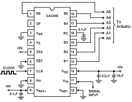
Here is the CA3306 schematic diagram;

Here is the code. It uses two push buttons, one on D12 and one on D13 to select the sample rate and the trigger level. To be honest the trigger does not work very well yet.
//**************************************** // Three color 5msps ext AtoD Scope // By Bob Davis // UTFT_(C)2012 Henning Karlsen // web: http://www.henningkarlsen.com/electronics // // Switches on D12 & D13 determine sweep speed and trigger level //******************************************* #include// Declare which fonts we will be using extern uint8_t SmallFont[]; extern uint8_t BigFont[]; extern uint8_t SevenSegNumFont[]; // Note that the control pins are now assigned to 8-11 UTFT myGLCD(ILI9325C,8,9,10,11); int Input=0; byte Sample[320]; byte OldSample[320]; int StartSample=0; int EndSample=0; int MaxSample=0; int MinSample=0; int mode=0; int dTime=1; int Trigger=10; int SampleSize=0; int SampleTime=0; void DrawMarkers(){ myGLCD.setColor(0, 220, 0); myGLCD.drawLine(0, 0, 0, 240); myGLCD.drawLine(60, 0, 60, 240); myGLCD.drawLine(120, 0, 120, 240); myGLCD.drawLine(180, 0, 180, 240); myGLCD.drawLine(239, 0, 239, 240); myGLCD.drawLine(319, 0, 319, 240); myGLCD.drawLine(0, 0, 319, 0); myGLCD.drawLine(0, 60, 319, 60); myGLCD.drawLine(0, 120, 319, 120); myGLCD.drawLine(0, 180, 319, 180); myGLCD.drawLine(0, 239, 319, 239); } void setup() { myGLCD.InitLCD(); myGLCD.clrScr(); pinMode(12, INPUT); digitalWrite(12, HIGH); pinMode(13, INPUT); digitalWrite(13, HIGH); pinMode(14, INPUT); pinMode(15, INPUT); pinMode(16, INPUT); pinMode(17, INPUT); pinMode(18, INPUT); pinMode(19, INPUT); } void loop() { // Set the background color(Red, Green, Blue) myGLCD.setBackColor(0, 0, 0); myGLCD.setFont(BigFont); char buf[12]; while(1) { DrawMarkers(); if (digitalRead(13) == 0) mode++; if (mode > 10) mode=0; // Select delay times for scan modes if (mode == 0) dTime=0; if (mode == 1) dTime=0; if (mode == 2) dTime=1; if (mode == 3) dTime=2; if (mode == 4) dTime=5; if (mode == 5) dTime=10; if (mode == 6) dTime=20; if (mode == 7) dTime=50; if (mode == 8) dTime=100; if (mode == 9) dTime=200; if (mode == 10) dTime=500; // Select trigger level if (digitalRead(12) == 0) Trigger=Trigger+10; if (Trigger > 50) Trigger=0; // Wait for input to be greater than trigger while (Input < Trigger){ Input = PINC; } // Collect the analog data into an array if (mode == 0) { // Read analog port as a parallel port no loop StartSample = micros(); Sample[0]=PINC; Sample[1]=PINC; Sample[2]=PINC; Sample[3]=PINC; Sample[4]=PINC; Sample[5]=PINC; Sample[6]=PINC; Sample[7]=PINC; Sample[8]=PINC; Sample[9]=PINC; Sample[10]=PINC; Sample[11]=PINC; Sample[12]=PINC; Sample[13]=PINC; Sample[14]=PINC; Sample[15]=PINC; Sample[16]=PINC; Sample[17]=PINC; Sample[18]=PINC; Sample[19]=PINC; Sample[20]=PINC; Sample[21]=PINC; Sample[22]=PINC; Sample[23]=PINC; Sample[24]=PINC; Sample[25]=PINC; Sample[26]=PINC; Sample[27]=PINC; Sample[28]=PINC; Sample[29]=PINC; Sample[30]=PINC; Sample[31]=PINC; Sample[32]=PINC; Sample[33]=PINC; Sample[34]=PINC; Sample[35]=PINC; Sample[36]=PINC; Sample[37]=PINC; Sample[38]=PINC; Sample[39]=PINC; Sample[40]=PINC; Sample[41]=PINC; Sample[42]=PINC; Sample[43]=PINC; Sample[44]=PINC; Sample[45]=PINC; Sample[46]=PINC; Sample[47]=PINC; Sample[48]=PINC; Sample[49]=PINC; Sample[50]=PINC; Sample[51]=PINC; Sample[52]=PINC; Sample[53]=PINC; Sample[54]=PINC; Sample[55]=PINC; Sample[56]=PINC; Sample[57]=PINC; Sample[58]=PINC; Sample[59]=PINC; Sample[60]=PINC; Sample[61]=PINC; Sample[62]=PINC; Sample[63]=PINC; Sample[64]=PINC; Sample[65]=PINC; Sample[66]=PINC; Sample[67]=PINC; Sample[68]=PINC; Sample[69]=PINC; Sample[70]=PINC; Sample[71]=PINC; Sample[72]=PINC; Sample[73]=PINC; Sample[74]=PINC; Sample[75]=PINC; Sample[76]=PINC; Sample[77]=PINC; Sample[78]=PINC; Sample[79]=PINC; Sample[80]=PINC; Sample[81]=PINC; Sample[82]=PINC; Sample[83]=PINC; Sample[84]=PINC; Sample[85]=PINC; Sample[86]=PINC; Sample[87]=PINC; Sample[88]=PINC; Sample[89]=PINC; Sample[90]=PINC; Sample[91]=PINC; Sample[92]=PINC; Sample[93]=PINC; Sample[94]=PINC; Sample[95]=PINC; Sample[96]=PINC; Sample[97]=PINC; Sample[98]=PINC; Sample[99]=PINC; Sample[100]=PINC; Sample[101]=PINC; Sample[102]=PINC; Sample[103]=PINC; Sample[104]=PINC; Sample[105]=PINC; Sample[106]=PINC; Sample[107]=PINC; Sample[108]=PINC; Sample[109]=PINC; Sample[110]=PINC; Sample[111]=PINC; Sample[112]=PINC; Sample[113]=PINC; Sample[114]=PINC; Sample[115]=PINC; Sample[116]=PINC; Sample[117]=PINC; Sample[118]=PINC; Sample[119]=PINC; Sample[120]=PINC; Sample[121]=PINC; Sample[122]=PINC; Sample[123]=PINC; Sample[124]=PINC; Sample[125]=PINC; Sample[126]=PINC; Sample[127]=PINC; Sample[128]=PINC; Sample[129]=PINC; Sample[130]=PINC; Sample[131]=PINC; Sample[132]=PINC; Sample[133]=PINC; Sample[134]=PINC; Sample[135]=PINC; Sample[136]=PINC; Sample[137]=PINC; Sample[138]=PINC; Sample[139]=PINC; Sample[140]=PINC; Sample[141]=PINC; Sample[142]=PINC; Sample[143]=PINC; Sample[144]=PINC; Sample[145]=PINC; Sample[146]=PINC; Sample[147]=PINC; Sample[148]=PINC; Sample[149]=PINC; Sample[150]=PINC; Sample[151]=PINC; Sample[152]=PINC; Sample[153]=PINC; Sample[154]=PINC; Sample[155]=PINC; Sample[156]=PINC; Sample[157]=PINC; Sample[158]=PINC; Sample[159]=PINC; Sample[160]=PINC; Sample[161]=PINC; Sample[162]=PINC; Sample[163]=PINC; Sample[164]=PINC; Sample[165]=PINC; Sample[166]=PINC; Sample[167]=PINC; Sample[168]=PINC; Sample[169]=PINC; Sample[170]=PINC; Sample[171]=PINC; Sample[172]=PINC; Sample[173]=PINC; Sample[174]=PINC; Sample[175]=PINC; Sample[176]=PINC; Sample[177]=PINC; Sample[178]=PINC; Sample[179]=PINC; Sample[180]=PINC; Sample[181]=PINC; Sample[182]=PINC; Sample[183]=PINC; Sample[184]=PINC; Sample[185]=PINC; Sample[186]=PINC; Sample[187]=PINC; Sample[188]=PINC; Sample[189]=PINC; Sample[190]=PINC; Sample[191]=PINC; Sample[192]=PINC; Sample[193]=PINC; Sample[194]=PINC; Sample[195]=PINC; Sample[196]=PINC; Sample[197]=PINC; Sample[198]=PINC; Sample[199]=PINC; Sample[200]=PINC; Sample[201]=PINC; Sample[202]=PINC; Sample[203]=PINC; Sample[204]=PINC; Sample[205]=PINC; Sample[206]=PINC; Sample[207]=PINC; Sample[208]=PINC; Sample[209]=PINC; Sample[210]=PINC; Sample[211]=PINC; Sample[212]=PINC; Sample[213]=PINC; Sample[214]=PINC; Sample[215]=PINC; Sample[216]=PINC; Sample[217]=PINC; Sample[218]=PINC; Sample[219]=PINC; Sample[220]=PINC; Sample[221]=PINC; Sample[222]=PINC; Sample[223]=PINC; Sample[224]=PINC; Sample[225]=PINC; Sample[226]=PINC; Sample[227]=PINC; Sample[228]=PINC; Sample[229]=PINC; Sample[230]=PINC; Sample[231]=PINC; Sample[232]=PINC; Sample[233]=PINC; Sample[234]=PINC; Sample[235]=PINC; Sample[236]=PINC; Sample[237]=PINC; Sample[238]=PINC; Sample[239]=PINC; Sample[240]=PINC; EndSample = micros(); } if (mode == 1) { // Read analog port as a parallel port no delay StartSample = micros(); for(int xpos=0; xpos<240; xpos++) { Sample[xpos]=PINC; } EndSample = micros(); } if (mode >= 2) { // Read analog port as a parallel port variable delay StartSample = micros(); for(int xpos=0; xpos<240; xpos++) { Sample[xpos]=PINC; delayMicroseconds(dTime); } EndSample = micros(); } // Display the collected analog data from array for(int xpos=0; xpos<239; xpos++) { // Erase the old stuff myGLCD.setColor(0, 0, 0); myGLCD.drawLine (xpos+1, 255-OldSample[xpos+1]*4, xpos+2, 255-OldSample[xpos+2]*4); if (xpos==0) myGLCD.drawLine (xpos+1, 1, xpos+1, 239); // Draw the new data myGLCD.setColor(255, 255, 255); myGLCD.drawLine (xpos, 255-Sample[xpos]*4, xpos+1, 255-Sample[xpos+1]*4); } // Determine sample voltage peak to peak MaxSample = Sample[100]; MinSample = Sample[100]; for(int xpos=0; xpos<240; xpos++) { OldSample[xpos] = Sample[xpos]; if (Sample[xpos] > MaxSample) MaxSample=Sample[xpos]; if (Sample[xpos] < MinSample) MinSample=Sample[xpos]; } // display the sample time, delay time and trigger level myGLCD.setColor(0, 0, 255); SampleTime=EndSample-StartSample; myGLCD.print("uSec.", 240, 10); myGLCD.print(" ", 240, 30); myGLCD.print(itoa(SampleTime, buf, 10), 240, 30); myGLCD.print("Delay", 240, 70); myGLCD.print(" ", 240, 90); myGLCD.print(itoa(dTime, buf, 10), 240, 90); myGLCD.print("Trig.", 240, 130); myGLCD.print(itoa(Trigger, buf, 10), 240, 150); // Range of 0 to 64 * 78 = 4992 mV SampleSize=(MaxSample-MinSample)*78; myGLCD.print("mVolt", 240, 190); myGLCD.print(itoa(SampleSize, buf, 10), 240, 210); } }
11 comments:
This is great! I was trying to make my own DSO too, But I was trying to use an ADC from Texas Instruments. I got a question. Where are you generating the clock signal for the ADC? I was using one pin of the arduino to generate the clock signal, and it wasnt very fast. With a bare stellaris launchpad, I can get almost 1Msps, check this out, http://patolin.com/blog/2013/07/07/osciloscopio-con-stellaris-launchpad-actualizacion/
check out the pga113 as your scope frontend. It's super easy to use
Great project! Before I used MCP3xxx or the ADS7818 ADCs, but with maximum speed of 2 x 250ksps. I expand this project to two channels, channel one on Arduino Pin A0...A5, channel two on D0...D5. The GLCD Display is a little bit smaller (ITDB02-2.2SP) with SPI Connection on Pin D9,D10,D11 and D13 with UTFT-Lib). For 2x200 samples it needs about 80µs (2x2,5 Msps).
how to give the clock from arduino?Secondly how to do the same withe arduino Mega2560?
I have not solved the clock problem yet. Try using a 16MHz clock and then jumpering it through a small cap to the Arduino clock (pin 9 I think).
Great work! Is the above schematic complete? It doesn't seem to show all the parts. Am I missing something?
The schematic does not show the analog input section or the LCD screen. They can be found in my book "Arduino Oscilloscope Projects".
Great book with LOTS of detail! Nice work! I'll work on putting one of these together with the TLC5510 one day.
Hey Bob, maybe I'm late to the party but I was wondering a few things.
1- Why not using 2 CA3306 ADCs phased out to be able to reach 10 MSamples? (I know for a fact that Rigol is doing such a thing on their cheaper models. Even Overclocking them).
2- What about using a cortex-m0 or even m3 board? (they are really cheap nowadays, they can be integrated on the Arduino IDE). I saw those boards compared with Arduino generating graphics on a screen and... THEY ARE REALLY FAST in comparison to Arduino!
These are just a couple of ideas.
I would appreciate your opinion about them, and why yes or why not, and alternatives to it. If my ideas are not interesting enough but I can, somehow, spark new ideas ... I'll be happy with that! ^_^
Hi, I have built a smally oscilloscope based in your hardware desing. I am very happy.
https://photos.google.com/album/AF1QipPfXUX9jlv3FZofZsjz8ngC4-AHvW7Q38do_rEL/photo/AF1QipPwAbZdfWrwhlI3txH-mY8y99Ay_3JK72261FvV
DIYFanatic - You can overclock the Arduino and even sync it with an ADC, but that is not something the average person can easily do. If you use an external oscillator and inject the signal to pin 9 (If I remember right) then the Arduino will run much faster.
Post a Comment