I was tempted to call this the 1400 amplifier repair from hell. It needed more repairs than any other amplifier that I have fixed in the past. It started off with the usual 3K at two watt resistor being fried. That caused one of the OP amps to have only four volts on pin eight instead of 15 volts like when it is working properly. Simple enough, replace it. I did not have a 3K two watt resistor so I used three 1K one watt resistors in series.
When the amplifier still did not work, I checked the 3.9 volt zener diodes, they another common part to fail. However they were both good. Then I noticed that the idle output of the OP amp was at three volts. If I remove the OP amp, the positive input was still at .3 volts, that in turn would cause the OP amp to output 3 volts and that pushed the amplifier output to over 30 volts at idle. So where was the .3 volts coming from?
First you need to know that QSC amplifiers work like no other amplifier. The "ground" floats, the output transistors are directly mounted on the heat sink without an insulator, there is no center tap on the power transformer to be a ground. So a ground reference is created with two matched resistors, one to +75 and one to -75 volts. The middle of the resistors should be at zero volts. That was where the problem was, one of the two matched resistors was open. I had to replace both of them so they match, and I did not have 47K at one watt so I used two 100K at 1/2 watt resistors in parallel for each of the two 47K resistors.
Here is the schematic, I circled the blown parts in red.
Here is a picture of the repaired amplifier, red arrows point out the replaced parts.
Now I said this was a difficult repair, that is because there were two other repairs that I made along the way. At some point I noticed that there was a resistor that was not properly soldered in. When I soldered it, the amplifier went into shut down and would not power up. The next problem turned out to be a bad connection on the heat sensor that is mounted on the heat sink. With those two additional repairs, the amplifier was finally up and running.
Wednesday, August 14, 2013
Tuesday, August 13, 2013
I need your help getting to the top in Amazon books
If you have read any of my books and liked them PLEASE go to Amazon and give it a positive review. So far most of my books only have one review, and I need to have lots of positive reviews to get to the top in Amazon searches. Most of my books are available in both printed and Kindle versions. THANKS!
Here are some of my books:
Arduino LED Projects: www.amazon.com/Arduino-L-E-D-Projects-ebook/dp/B00C4YY9DY/
Arduino LCD Projects: http://www.amazon.com/Arduino-LCD-Projects-Robert-Davis/dp/1490980709
Fringe Electronic 'Medical' Devices: http://www.amazon.com/Fringe-Electronic-Medical-Devices-Robert/dp/1491042494
Creation is a Fact!: www.amazon.com/Creation-Fact-Scientific-Historical-Evidence/dp/1491220597
Here are some of my books:
Arduino LED Projects: www.amazon.com/Arduino-L-E-D-Projects-ebook/dp/B00C4YY9DY/
Arduino LCD Projects: http://www.amazon.com/Arduino-LCD-Projects-Robert-Davis/dp/1490980709
Fringe Electronic 'Medical' Devices: http://www.amazon.com/Fringe-Electronic-Medical-Devices-Robert/dp/1491042494
Creation is a Fact!: www.amazon.com/Creation-Fact-Scientific-Historical-Evidence/dp/1491220597
The supposed upcoming worldwide solar tsunami predicted by Snowden
I looked on the "Truth or fiction" web site and cannot find anythig on this, so I thought I would give my opinion here.
IT IS PURELY FICTION!
Here is what our sun looks like now according to NASA;
I have been reading about this, but like the Y2K problem, and the Mayan calendar, I have issues with it.
* First solar reversal happens every 11 years so this is nothing new or unusual.
* Second the impact of solar storms is totally unpredictable, most miss the earth.
* Third the greatest effect will be on things attached to long wires, like telephone and power lines, NOT on your computer or car.
On the other hand the loss of our power grid would lead to the loss of gas for your car and gas for delivering food. As always have a six month supply of food and water on hand. Some say to have a years supply.
What they are talking about is called the "Carrington" effect. Back in like 1859 or something like that, a solar storm fried the telegraph wires. By the way, these days our power grid has lots of protection, it takes direct lightning strikes and keeps on working....
All of these false "End of the World" things are to take your mind away from the REAL problem: We are at a far greater risk of a worldwide economic collapse brought on by the actions of our government and the bankers.....
IT IS PURELY FICTION!
Here is what our sun looks like now according to NASA;
I have been reading about this, but like the Y2K problem, and the Mayan calendar, I have issues with it.
* First solar reversal happens every 11 years so this is nothing new or unusual.
* Second the impact of solar storms is totally unpredictable, most miss the earth.
* Third the greatest effect will be on things attached to long wires, like telephone and power lines, NOT on your computer or car.
On the other hand the loss of our power grid would lead to the loss of gas for your car and gas for delivering food. As always have a six month supply of food and water on hand. Some say to have a years supply.
What they are talking about is called the "Carrington" effect. Back in like 1859 or something like that, a solar storm fried the telegraph wires. By the way, these days our power grid has lots of protection, it takes direct lightning strikes and keeps on working....
All of these false "End of the World" things are to take your mind away from the REAL problem: We are at a far greater risk of a worldwide economic collapse brought on by the actions of our government and the bankers.....
Sunday, August 11, 2013
Installing my first addressable alarm system
During the last two weekends I have spent some time back up at Elim installing a new alarm system. It is the first addressable alarm system that I have ever worked with. The alarm company wanted all new wiring so there were lots of wires to run as well. The specs called for strobes or horn/strobes in every room, so the alarm panel needed a booster panel to run all of those alarm devices.
I have now had a hand in replacing the 110 volt systems with 24 volt systems and then replacing the 24 volt systems with an addressable system.
While I was there the wood started arriving to fix the roof of the Tab. The moral of that story is to never put a flat room under an angled roof. The snow falls off the angled roof and piles up on the flat roof. Then the snow melts but the water cannot get through the drift. Then the water leaks down into the rooms below.
I have now had a hand in replacing the 110 volt systems with 24 volt systems and then replacing the 24 volt systems with an addressable system.
While I was there the wood started arriving to fix the roof of the Tab. The moral of that story is to never put a flat room under an angled roof. The snow falls off the angled roof and piles up on the flat roof. Then the snow melts but the water cannot get through the drift. Then the water leaks down into the rooms below.
Wednesday, July 31, 2013
Radio Shack Desoldering Tool
I rarely endorse things, and I do not get a penny for endorsing things when I do.
Recently I need to de-solder some transistors. They were in a very tight space and getting a solder sucking tool on one side and a soldering iron on the other side was not a possibility. So I looked at getting an all in one tool. I was looking on eBay when someone nearby said that they had one for the same price at Radio Shack. I could not believe it, but sure enough it was at the same price. So I bought it and had the chance to use it. Let me say I was very impressed, it worked perfectly.
Here is the same tool from another angle. It is well worth the $15 price tag.
Recently I need to de-solder some transistors. They were in a very tight space and getting a solder sucking tool on one side and a soldering iron on the other side was not a possibility. So I looked at getting an all in one tool. I was looking on eBay when someone nearby said that they had one for the same price at Radio Shack. I could not believe it, but sure enough it was at the same price. So I bought it and had the chance to use it. Let me say I was very impressed, it worked perfectly.
Here is the same tool from another angle. It is well worth the $15 price tag.
Saturday, July 20, 2013
Batavia NY Hamfest
Today I attended the Batavia NY Hamfest. It is actually located at the Alexander Firemen Grounds on 98 south of Batavia. To be honest it might have been the worse one ever. I did sell a couple of items but then it started raining. They opened up the pavilions to anyone so I moved to where there was a roof over my head, but I still did not sell much.
On the bright side I bought the least amount of stuff that I have ever bought at an Hamfest. All I bought was a hamburg! There were some really nice oscilloscopes and even a scope meter, but I did not have a chance to buy anything before it started raining.
here is a picture of the pavilion that I moved to.
This was my setup before it started raining. I moved everything I could into the back of the van when it started raining.
On the bright side I bought the least amount of stuff that I have ever bought at an Hamfest. All I bought was a hamburg! There were some really nice oscilloscopes and even a scope meter, but I did not have a chance to buy anything before it started raining.
here is a picture of the pavilion that I moved to.
This was my setup before it started raining. I moved everything I could into the back of the van when it started raining.
Chaffee NY Hamfest
Back on June 11 I went to the Chaffee NY Hamfest. It was only the second time that I have been there. I just today discovered that I have not posted about the Hamfests that I have been attending for about 2 or 3 years. Even this post is a month late!
I thought that this radio was an amazing find.
Here is my spot, I mostly sold books.
This is what it looked like, there were not a lot of people there.
I thought that this radio was an amazing find.
Here is my spot, I mostly sold books.
This is what it looked like, there were not a lot of people there.
Sunday, July 14, 2013
Gateway MS2274 Power Button Repair
I recently had a Gateway MS2274 laptop come in for repairs. It was totally dead. The hinges were in rough shape and some screws were missing. The power cord had broken and was taped together in two spots. I searched around and found another adapter but the laptop was still dead. I started taking it apart and when I located where to power button plugs in I jumpered my screwdriver across it. The laptop powered on and worked! So I went on eBay and purchased a replacement.
To disassemble it there is a screw hidden on the backside of the screen hinge as well as two screws inside of the battery compartment.
Here is the removed power switch, actually just the cord to it was bad.
Here is where the power switch is located. You have to remove the piece above the keyboard as well as some screen screws to get to it.
This is another picture of the power switch, it is hard to get it back together.
Here is the screw that is hidden on the back side of the hinge.
To disassemble it there is a screw hidden on the backside of the screen hinge as well as two screws inside of the battery compartment.
Here is the removed power switch, actually just the cord to it was bad.
Here is where the power switch is located. You have to remove the piece above the keyboard as well as some screen screws to get to it.
This is another picture of the power switch, it is hard to get it back together.
Here is the screw that is hidden on the back side of the hinge.
Monday, July 8, 2013
Arduino powered 5 Million samples per second oscope with CA3306 Part 2
It is easier for me to add another part to the previous post, than to edit that one because if I do blogger will totally trash my code. Someone asked about the LCD display connections, etc. First the LCD is the common 2.4 inch LCD found on eBay. It is identified by having 18 pins at one end and two sets of pins that are perpendicular to that for the touch screen and memory card.
here is a picture of the backside of the LCD showing how the connectors are arranged.
Here is a schematic of the LCD hookup with the control pins changed so the analog ports are free.
Here is a picture of the LCD hookup for the 5 million sample per second oscilloscope.
Someone on "Hack A Day" pointed out that I left off the oscillator schematic. Here is a schematic of the clock. It can be any clock oscillator from 5 to 10 MC.
here is a picture of the backside of the LCD showing how the connectors are arranged.
Here is a schematic of the LCD hookup with the control pins changed so the analog ports are free.
Here is a picture of the LCD hookup for the 5 million sample per second oscilloscope.
Someone on "Hack A Day" pointed out that I left off the oscillator schematic. Here is a schematic of the clock. It can be any clock oscillator from 5 to 10 MC.
Thursday, June 27, 2013
Arduino powered 5 Million samples per second oscope with CA3306
This Arduino powered 5 Million samples per second oscilloscope uses an external CA3306 analog to digital converter. the Ca3306 produces less glitches than the AD775 did. Here is the video on YouTube. http://youtu.be/f_RD1oQuKiw I fixed the memory issue and even sped it up some more by changing the array from 320 integers to 240 bytes. Integers are 16 bits long and bytes are 8 bits long, so it is much faster and uses less memory.
I also added a trigger and speed selection switch on D12 and D13 to ground. The speed selection has 10 modes. They range from no loop, to a loop with no delay, to eight available delay settings.
Here is a picture of the screen of the oscilloscope running in its fastest mode.
Here is a picture of the CA3306 wiring, it is much easier than the other Analog to digital converter was.
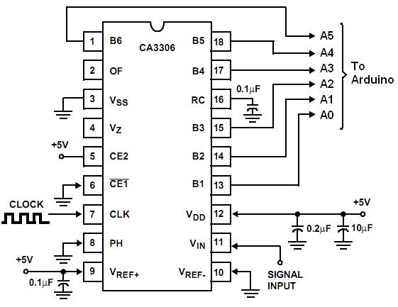
Here is the CA3306 schematic diagram;
Here is a oscilloscope like input section schematic. I used two 9 volt batteries to test it out. It give the ability to handle inputs of up to 50 volts and also allows gain selection. It is a much simpler design than the input section that was in my book "Digital and Computer projects".
Here is the code. It uses two push buttons, one on D12 and one on D13 to select the sample rate and the trigger level. To be honest the trigger does not work very well yet.
I also added a trigger and speed selection switch on D12 and D13 to ground. The speed selection has 10 modes. They range from no loop, to a loop with no delay, to eight available delay settings.
Here is a picture of the screen of the oscilloscope running in its fastest mode.
Here is a picture of the CA3306 wiring, it is much easier than the other Analog to digital converter was.
Here is the CA3306 schematic diagram;
Here is a oscilloscope like input section schematic. I used two 9 volt batteries to test it out. It give the ability to handle inputs of up to 50 volts and also allows gain selection. It is a much simpler design than the input section that was in my book "Digital and Computer projects".
Here is the code. It uses two push buttons, one on D12 and one on D13 to select the sample rate and the trigger level. To be honest the trigger does not work very well yet.
//**************************************** // Three color 5msps ext AtoD Scope // By Bob Davis // UTFT_(C)2012 Henning Karlsen // web: http://www.henningkarlsen.com/electronics // // Switches on D12 & D13 determine sweep speed and trigger level //******************************************* #include// Declare which fonts we will be using extern uint8_t SmallFont[]; extern uint8_t BigFont[]; extern uint8_t SevenSegNumFont[]; // Note that the control pins are now assigned to 8-11 UTFT myGLCD(ILI9325C,8,9,10,11); int Input=0; byte Sample[320]; byte OldSample[320]; int StartSample=0; int EndSample=0; int MaxSample=0; int MinSample=0; int mode=0; int dTime=1; int Trigger=10; int SampleSize=0; int SampleTime=0; void DrawMarkers(){ myGLCD.setColor(0, 220, 0); myGLCD.drawLine(0, 0, 0, 240); myGLCD.drawLine(60, 0, 60, 240); myGLCD.drawLine(120, 0, 120, 240); myGLCD.drawLine(180, 0, 180, 240); myGLCD.drawLine(239, 0, 239, 240); myGLCD.drawLine(319, 0, 319, 240); myGLCD.drawLine(0, 0, 319, 0); myGLCD.drawLine(0, 60, 319, 60); myGLCD.drawLine(0, 120, 319, 120); myGLCD.drawLine(0, 180, 319, 180); myGLCD.drawLine(0, 239, 319, 239); } void setup() { myGLCD.InitLCD(); myGLCD.clrScr(); pinMode(12, INPUT); digitalWrite(12, HIGH); pinMode(13, INPUT); digitalWrite(13, HIGH); pinMode(14, INPUT); pinMode(15, INPUT); pinMode(16, INPUT); pinMode(17, INPUT); pinMode(18, INPUT); pinMode(19, INPUT); } void loop() { // Set the background color(Red, Green, Blue) myGLCD.setBackColor(0, 0, 0); myGLCD.setFont(BigFont); char buf[12]; while(1) { DrawMarkers(); if (digitalRead(13) == 0) mode++; if (mode > 10) mode=0; // Select delay times for scan modes if (mode == 0) dTime=0; if (mode == 1) dTime=0; if (mode == 2) dTime=1; if (mode == 3) dTime=2; if (mode == 4) dTime=5; if (mode == 5) dTime=10; if (mode == 6) dTime=20; if (mode == 7) dTime=50; if (mode == 8) dTime=100; if (mode == 9) dTime=200; if (mode == 10) dTime=500; // Select trigger level if (digitalRead(12) == 0) Trigger=Trigger+10; if (Trigger > 50) Trigger=0; // Wait for input to be greater than trigger while (Input < Trigger){ Input = PINC; } // Collect the analog data into an array if (mode == 0) { // Read analog port as a parallel port no loop StartSample = micros(); Sample[0]=PINC; Sample[1]=PINC; Sample[2]=PINC; Sample[3]=PINC; Sample[4]=PINC; Sample[5]=PINC; Sample[6]=PINC; Sample[7]=PINC; Sample[8]=PINC; Sample[9]=PINC; Sample[10]=PINC; Sample[11]=PINC; Sample[12]=PINC; Sample[13]=PINC; Sample[14]=PINC; Sample[15]=PINC; Sample[16]=PINC; Sample[17]=PINC; Sample[18]=PINC; Sample[19]=PINC; Sample[20]=PINC; Sample[21]=PINC; Sample[22]=PINC; Sample[23]=PINC; Sample[24]=PINC; Sample[25]=PINC; Sample[26]=PINC; Sample[27]=PINC; Sample[28]=PINC; Sample[29]=PINC; Sample[30]=PINC; Sample[31]=PINC; Sample[32]=PINC; Sample[33]=PINC; Sample[34]=PINC; Sample[35]=PINC; Sample[36]=PINC; Sample[37]=PINC; Sample[38]=PINC; Sample[39]=PINC; Sample[40]=PINC; Sample[41]=PINC; Sample[42]=PINC; Sample[43]=PINC; Sample[44]=PINC; Sample[45]=PINC; Sample[46]=PINC; Sample[47]=PINC; Sample[48]=PINC; Sample[49]=PINC; Sample[50]=PINC; Sample[51]=PINC; Sample[52]=PINC; Sample[53]=PINC; Sample[54]=PINC; Sample[55]=PINC; Sample[56]=PINC; Sample[57]=PINC; Sample[58]=PINC; Sample[59]=PINC; Sample[60]=PINC; Sample[61]=PINC; Sample[62]=PINC; Sample[63]=PINC; Sample[64]=PINC; Sample[65]=PINC; Sample[66]=PINC; Sample[67]=PINC; Sample[68]=PINC; Sample[69]=PINC; Sample[70]=PINC; Sample[71]=PINC; Sample[72]=PINC; Sample[73]=PINC; Sample[74]=PINC; Sample[75]=PINC; Sample[76]=PINC; Sample[77]=PINC; Sample[78]=PINC; Sample[79]=PINC; Sample[80]=PINC; Sample[81]=PINC; Sample[82]=PINC; Sample[83]=PINC; Sample[84]=PINC; Sample[85]=PINC; Sample[86]=PINC; Sample[87]=PINC; Sample[88]=PINC; Sample[89]=PINC; Sample[90]=PINC; Sample[91]=PINC; Sample[92]=PINC; Sample[93]=PINC; Sample[94]=PINC; Sample[95]=PINC; Sample[96]=PINC; Sample[97]=PINC; Sample[98]=PINC; Sample[99]=PINC; Sample[100]=PINC; Sample[101]=PINC; Sample[102]=PINC; Sample[103]=PINC; Sample[104]=PINC; Sample[105]=PINC; Sample[106]=PINC; Sample[107]=PINC; Sample[108]=PINC; Sample[109]=PINC; Sample[110]=PINC; Sample[111]=PINC; Sample[112]=PINC; Sample[113]=PINC; Sample[114]=PINC; Sample[115]=PINC; Sample[116]=PINC; Sample[117]=PINC; Sample[118]=PINC; Sample[119]=PINC; Sample[120]=PINC; Sample[121]=PINC; Sample[122]=PINC; Sample[123]=PINC; Sample[124]=PINC; Sample[125]=PINC; Sample[126]=PINC; Sample[127]=PINC; Sample[128]=PINC; Sample[129]=PINC; Sample[130]=PINC; Sample[131]=PINC; Sample[132]=PINC; Sample[133]=PINC; Sample[134]=PINC; Sample[135]=PINC; Sample[136]=PINC; Sample[137]=PINC; Sample[138]=PINC; Sample[139]=PINC; Sample[140]=PINC; Sample[141]=PINC; Sample[142]=PINC; Sample[143]=PINC; Sample[144]=PINC; Sample[145]=PINC; Sample[146]=PINC; Sample[147]=PINC; Sample[148]=PINC; Sample[149]=PINC; Sample[150]=PINC; Sample[151]=PINC; Sample[152]=PINC; Sample[153]=PINC; Sample[154]=PINC; Sample[155]=PINC; Sample[156]=PINC; Sample[157]=PINC; Sample[158]=PINC; Sample[159]=PINC; Sample[160]=PINC; Sample[161]=PINC; Sample[162]=PINC; Sample[163]=PINC; Sample[164]=PINC; Sample[165]=PINC; Sample[166]=PINC; Sample[167]=PINC; Sample[168]=PINC; Sample[169]=PINC; Sample[170]=PINC; Sample[171]=PINC; Sample[172]=PINC; Sample[173]=PINC; Sample[174]=PINC; Sample[175]=PINC; Sample[176]=PINC; Sample[177]=PINC; Sample[178]=PINC; Sample[179]=PINC; Sample[180]=PINC; Sample[181]=PINC; Sample[182]=PINC; Sample[183]=PINC; Sample[184]=PINC; Sample[185]=PINC; Sample[186]=PINC; Sample[187]=PINC; Sample[188]=PINC; Sample[189]=PINC; Sample[190]=PINC; Sample[191]=PINC; Sample[192]=PINC; Sample[193]=PINC; Sample[194]=PINC; Sample[195]=PINC; Sample[196]=PINC; Sample[197]=PINC; Sample[198]=PINC; Sample[199]=PINC; Sample[200]=PINC; Sample[201]=PINC; Sample[202]=PINC; Sample[203]=PINC; Sample[204]=PINC; Sample[205]=PINC; Sample[206]=PINC; Sample[207]=PINC; Sample[208]=PINC; Sample[209]=PINC; Sample[210]=PINC; Sample[211]=PINC; Sample[212]=PINC; Sample[213]=PINC; Sample[214]=PINC; Sample[215]=PINC; Sample[216]=PINC; Sample[217]=PINC; Sample[218]=PINC; Sample[219]=PINC; Sample[220]=PINC; Sample[221]=PINC; Sample[222]=PINC; Sample[223]=PINC; Sample[224]=PINC; Sample[225]=PINC; Sample[226]=PINC; Sample[227]=PINC; Sample[228]=PINC; Sample[229]=PINC; Sample[230]=PINC; Sample[231]=PINC; Sample[232]=PINC; Sample[233]=PINC; Sample[234]=PINC; Sample[235]=PINC; Sample[236]=PINC; Sample[237]=PINC; Sample[238]=PINC; Sample[239]=PINC; Sample[240]=PINC; EndSample = micros(); } if (mode == 1) { // Read analog port as a parallel port no delay StartSample = micros(); for(int xpos=0; xpos<240; xpos++) { Sample[xpos]=PINC; } EndSample = micros(); } if (mode >= 2) { // Read analog port as a parallel port variable delay StartSample = micros(); for(int xpos=0; xpos<240; xpos++) { Sample[xpos]=PINC; delayMicroseconds(dTime); } EndSample = micros(); } // Display the collected analog data from array for(int xpos=0; xpos<239; xpos++) { // Erase the old stuff myGLCD.setColor(0, 0, 0); myGLCD.drawLine (xpos+1, 255-OldSample[xpos+1]*4, xpos+2, 255-OldSample[xpos+2]*4); if (xpos==0) myGLCD.drawLine (xpos+1, 1, xpos+1, 239); // Draw the new data myGLCD.setColor(255, 255, 255); myGLCD.drawLine (xpos, 255-Sample[xpos]*4, xpos+1, 255-Sample[xpos+1]*4); } // Determine sample voltage peak to peak MaxSample = Sample[100]; MinSample = Sample[100]; for(int xpos=0; xpos<240; xpos++) { OldSample[xpos] = Sample[xpos]; if (Sample[xpos] > MaxSample) MaxSample=Sample[xpos]; if (Sample[xpos] < MinSample) MinSample=Sample[xpos]; } // display the sample time, delay time and trigger level myGLCD.setColor(0, 0, 255); SampleTime=EndSample-StartSample; myGLCD.print("uSec.", 240, 10); myGLCD.print(" ", 240, 30); myGLCD.print(itoa(SampleTime, buf, 10), 240, 30); myGLCD.print("Delay", 240, 70); myGLCD.print(" ", 240, 90); myGLCD.print(itoa(dTime, buf, 10), 240, 90); myGLCD.print("Trig.", 240, 130); myGLCD.print(itoa(Trigger, buf, 10), 240, 150); // Range of 0 to 64 * 78 = 4992 mV SampleSize=(MaxSample-MinSample)*78; myGLCD.print("mVolt", 240, 190); myGLCD.print(itoa(SampleSize, buf, 10), 240, 210); } }
Arduino Powered 10 Million samples per second Oscilloscope
I have created an Arduino Powered 10 Million samples per second Oscilloscope. It even works at 25 Million samples per second. The secret is using an external Analog to digital converter and a FIFO. Here is the video on YouTube.http://youtu.be/RcepVnXUlJY
Here is the schematic diagram.
Here is a picture of the wiring, it is a little complicated.
There is an optional 74LS10 that prevents writes to the FIFO once it is full. Otherwise about every 10 scans you will get a lot of garbage.
You could also add two 74LS390 dual divide by 10's and an ten position switch to have a method of selecting the recording frequency.
An op amplifier on the input would also improve the performance. Then you could select AC/DC coupling, Gain, and divide by 10 for input options. The position control works better with an op amp too.
Here is the schematic diagram.
Here is a picture of the wiring, it is a little complicated.
There is an optional 74LS10 that prevents writes to the FIFO once it is full. Otherwise about every 10 scans you will get a lot of garbage.
You could also add two 74LS390 dual divide by 10's and an ten position switch to have a method of selecting the recording frequency.
An op amplifier on the input would also improve the performance. Then you could select AC/DC coupling, Gain, and divide by 10 for input options. The position control works better with an op amp too.
Monday, June 24, 2013
Arduino 3 Million samples per second oscilloscope
I have built an Arduino powered 3 million samples per second oscilloscope. The secret to the speed is using an external Analog to Digital Converter. Here is the video on YouTube; http://youtu.be/fG7trChbg88
This is the schematic of the AD775 Fast analog to digital converter setup;
Here is a picture of the screen.
Here is the code for 3 million samples per second, to get that fast you need to say Sample[1]=PINC a total of 320 times!
This is the schematic of the AD775 Fast analog to digital converter setup;
Here is a picture of the screen.
Here is the code for 3 million samples per second, to get that fast you need to say Sample[1]=PINC a total of 320 times!
//**************************************** // Three color 3MspS ext AtoD Scope // By Bob Davis // UTFT_(C)2012 Henning Karlsen // web: http://www.henningkarlsen.com/electronics // #include// Declare which fonts we will be using extern uint8_t SmallFont[]; extern uint8_t BigFont[]; extern uint8_t SevenSegNumFont[]; // Note that control pins are now assigned to 8-11 UTFT myGLCD(ILI9325C,8,9,10,11); int Input=0; int Sample[320]; int StartSTime=0; int EndSTime=0; float SampleTime=0; void DrawMarkers(){ myGLCD.setColor(0, 200, 0); myGLCD.drawLine(0, 0, 0, 240); myGLCD.drawLine(54, 0, 54, 240); myGLCD.drawLine(107, 0, 107, 240); myGLCD.drawLine(160, 0, 160, 240); myGLCD.drawLine(213, 0, 213, 240); myGLCD.drawLine(266, 0, 266, 240); myGLCD.drawLine(319, 0, 319, 240); myGLCD.drawLine(0, 0, 319, 0); myGLCD.drawLine(0, 50, 319, 50); myGLCD.drawLine(0, 100, 319, 100); myGLCD.drawLine(0, 150, 319, 150); myGLCD.drawLine(0, 200, 319, 200); myGLCD.drawLine(0, 239, 319, 239); } void setup() { myGLCD.InitLCD(); myGLCD.clrScr(); pinMode(14, INPUT); pinMode(15, INPUT); pinMode(16, INPUT); pinMode(17, INPUT); pinMode(18, INPUT); pinMode(19, INPUT); } void loop() { // set color(Red, Green, Blue) range = 0 to 255 myGLCD.setBackColor(0, 0, 0); myGLCD.setFont(BigFont); char buf[12]; while(1) { DrawMarkers(); // wait for trigger of a positive input while (Input == 0){ Input = digitalRead(A1); } // collect the analog data into an array // Read analog port as a parallel port using PINC // Code with no loop is about 50% faster! StartSTime = micros(); Sample[0]=PINC; Sample[1]=PINC; Sample[2]=PINC; Sample[3]=PINC; Sample[4]=PINC; Sample[5]=PINC; Sample[6]=PINC; Sample[7]=PINC; Sample[8]=PINC; Sample[9]=PINC; Sample[10]=PINC; Sample[11]=PINC; Sample[12]=PINC; Sample[13]=PINC; Sample[14]=PINC; Sample[15]=PINC; Sample[16]=PINC; Sample[17]=PINC; Sample[18]=PINC; Sample[19]=PINC; Sample[20]=PINC; Sample[21]=PINC; Sample[22]=PINC; Sample[23]=PINC; Sample[24]=PINC; Sample[25]=PINC; Sample[26]=PINC; Sample[27]=PINC; Sample[28]=PINC; Sample[29]=PINC; Sample[30]=PINC; Sample[31]=PINC; Sample[32]=PINC; Sample[33]=PINC; Sample[34]=PINC; Sample[35]=PINC; Sample[36]=PINC; Sample[37]=PINC; Sample[38]=PINC; Sample[39]=PINC; Sample[40]=PINC; Sample[41]=PINC; Sample[42]=PINC; Sample[43]=PINC; Sample[44]=PINC; Sample[45]=PINC; Sample[46]=PINC; Sample[47]=PINC; Sample[48]=PINC; Sample[49]=PINC; Sample[50]=PINC; Sample[51]=PINC; Sample[52]=PINC; Sample[53]=PINC; Sample[54]=PINC; Sample[55]=PINC; Sample[56]=PINC; Sample[57]=PINC; Sample[58]=PINC; Sample[59]=PINC; Sample[60]=PINC; Sample[61]=PINC; Sample[62]=PINC; Sample[63]=PINC; Sample[64]=PINC; Sample[65]=PINC; Sample[66]=PINC; Sample[67]=PINC; Sample[68]=PINC; Sample[69]=PINC; Sample[70]=PINC; Sample[71]=PINC; Sample[72]=PINC; Sample[73]=PINC; Sample[74]=PINC; Sample[75]=PINC; Sample[76]=PINC; Sample[77]=PINC; Sample[78]=PINC; Sample[79]=PINC; Sample[80]=PINC; Sample[81]=PINC; Sample[82]=PINC; Sample[83]=PINC; Sample[84]=PINC; Sample[85]=PINC; Sample[86]=PINC; Sample[87]=PINC; Sample[88]=PINC; Sample[89]=PINC; Sample[90]=PINC; Sample[91]=PINC; Sample[92]=PINC; Sample[93]=PINC; Sample[94]=PINC; Sample[95]=PINC; Sample[96]=PINC; Sample[97]=PINC; Sample[98]=PINC; Sample[99]=PINC; Sample[100]=PINC; Sample[101]=PINC; Sample[102]=PINC; Sample[103]=PINC; Sample[104]=PINC; Sample[105]=PINC; Sample[106]=PINC; Sample[107]=PINC; Sample[108]=PINC; Sample[109]=PINC; Sample[110]=PINC; Sample[111]=PINC; Sample[112]=PINC; Sample[113]=PINC; Sample[114]=PINC; Sample[115]=PINC; Sample[116]=PINC; Sample[117]=PINC; Sample[118]=PINC; Sample[119]=PINC; Sample[120]=PINC; Sample[121]=PINC; Sample[122]=PINC; Sample[123]=PINC; Sample[124]=PINC; Sample[125]=PINC; Sample[126]=PINC; Sample[127]=PINC; Sample[128]=PINC; Sample[129]=PINC; Sample[130]=PINC; Sample[131]=PINC; Sample[132]=PINC; Sample[133]=PINC; Sample[134]=PINC; Sample[135]=PINC; Sample[136]=PINC; Sample[137]=PINC; Sample[138]=PINC; Sample[139]=PINC; Sample[140]=PINC; Sample[141]=PINC; Sample[142]=PINC; Sample[143]=PINC; Sample[144]=PINC; Sample[145]=PINC; Sample[146]=PINC; Sample[147]=PINC; Sample[148]=PINC; Sample[149]=PINC; Sample[150]=PINC; Sample[151]=PINC; Sample[152]=PINC; Sample[153]=PINC; Sample[154]=PINC; Sample[155]=PINC; Sample[156]=PINC; Sample[157]=PINC; Sample[158]=PINC; Sample[159]=PINC; Sample[160]=PINC; Sample[161]=PINC; Sample[162]=PINC; Sample[163]=PINC; Sample[164]=PINC; Sample[165]=PINC; Sample[166]=PINC; Sample[167]=PINC; Sample[168]=PINC; Sample[169]=PINC; Sample[170]=PINC; Sample[171]=PINC; Sample[172]=PINC; Sample[173]=PINC; Sample[174]=PINC; Sample[175]=PINC; Sample[176]=PINC; Sample[177]=PINC; Sample[178]=PINC; Sample[179]=PINC; Sample[180]=PINC; Sample[181]=PINC; Sample[182]=PINC; Sample[183]=PINC; Sample[184]=PINC; Sample[185]=PINC; Sample[186]=PINC; Sample[187]=PINC; Sample[188]=PINC; Sample[189]=PINC; Sample[190]=PINC; Sample[191]=PINC; Sample[192]=PINC; Sample[193]=PINC; Sample[194]=PINC; Sample[195]=PINC; Sample[196]=PINC; Sample[197]=PINC; Sample[198]=PINC; Sample[199]=PINC; Sample[200]=PINC; Sample[201]=PINC; Sample[202]=PINC; Sample[203]=PINC; Sample[204]=PINC; Sample[205]=PINC; Sample[206]=PINC; Sample[207]=PINC; Sample[208]=PINC; Sample[209]=PINC; Sample[210]=PINC; Sample[211]=PINC; Sample[212]=PINC; Sample[213]=PINC; Sample[214]=PINC; Sample[215]=PINC; Sample[216]=PINC; Sample[217]=PINC; Sample[218]=PINC; Sample[219]=PINC; Sample[220]=PINC; Sample[221]=PINC; Sample[222]=PINC; Sample[223]=PINC; Sample[224]=PINC; Sample[225]=PINC; Sample[226]=PINC; Sample[227]=PINC; Sample[228]=PINC; Sample[229]=PINC; Sample[230]=PINC; Sample[231]=PINC; Sample[232]=PINC; Sample[233]=PINC; Sample[234]=PINC; Sample[235]=PINC; Sample[236]=PINC; Sample[237]=PINC; Sample[238]=PINC; Sample[239]=PINC; Sample[240]=PINC; Sample[241]=PINC; Sample[242]=PINC; Sample[243]=PINC; Sample[244]=PINC; Sample[245]=PINC; Sample[246]=PINC; Sample[247]=PINC; Sample[248]=PINC; Sample[249]=PINC; Sample[250]=PINC; Sample[251]=PINC; Sample[252]=PINC; Sample[253]=PINC; Sample[254]=PINC; Sample[255]=PINC; Sample[256]=PINC; Sample[257]=PINC; Sample[258]=PINC; Sample[259]=PINC; Sample[260]=PINC; Sample[261]=PINC; Sample[262]=PINC; Sample[263]=PINC; Sample[264]=PINC; Sample[265]=PINC; Sample[266]=PINC; Sample[267]=PINC; Sample[268]=PINC; Sample[269]=PINC; Sample[270]=PINC; Sample[271]=PINC; Sample[272]=PINC; Sample[273]=PINC; Sample[274]=PINC; Sample[275]=PINC; Sample[276]=PINC; Sample[277]=PINC; Sample[278]=PINC; Sample[279]=PINC; Sample[280]=PINC; Sample[281]=PINC; Sample[282]=PINC; Sample[283]=PINC; Sample[284]=PINC; Sample[285]=PINC; Sample[286]=PINC; Sample[287]=PINC; Sample[288]=PINC; Sample[289]=PINC; Sample[290]=PINC; Sample[291]=PINC; Sample[292]=PINC; Sample[293]=PINC; Sample[294]=PINC; Sample[295]=PINC; Sample[296]=PINC; Sample[297]=PINC; Sample[298]=PINC; Sample[299]=PINC; Sample[300]=PINC; Sample[301]=PINC; Sample[302]=PINC; Sample[303]=PINC; Sample[304]=PINC; Sample[305]=PINC; Sample[306]=PINC; Sample[307]=PINC; Sample[308]=PINC; Sample[309]=PINC; Sample[310]=PINC; Sample[311]=PINC; Sample[312]=PINC; Sample[313]=PINC; Sample[314]=PINC; Sample[315]=PINC; Sample[316]=PINC; Sample[317]=PINC; Sample[318]=PINC; Sample[319]=PINC; EndSTime = micros(); // display the collected analog data from array for(int xpos=0; xpos<319; xpos++) { // Erase old stuff myGLCD.setColor(0, 0, 0); myGLCD.drawLine (xpos+1, 1, xpos+1, 180); // Draw new data if (xpos%10==0) DrawMarkers(); myGLCD.setColor(255, 255, 255); myGLCD.drawLine (xpos, Sample[xpos]*2, xpos+1, Sample[xpos+1]*2); } // display the sample time myGLCD.setColor(0, 0, 255); SampleTime = EndSTime - StartSTime; myGLCD.print("uSeconds= ", 10, 220); myGLCD.print(ltoa(SampleTime, buf, 10), 170, 220); } }
Thursday, June 20, 2013
Universal 8 Bit Graphics Library bug
A while back I posted a video that showed a strange bug that was happening with my oscilloscope LCD program. It used U8GLib or the Universal 8 Bit Graphics Library. The video is available at, http://youtu.be/1qPy6FVSllY
** UPDATE ** This problem is caused by updating the data while it is being displayed. The update must not happen within the display loop.
Then I made a perfectly working oscilloscope using the Universal TFT Library and a better LCD. So then I thought I would go back and see what was the problem with U8GLib.
To rule out the LCD display I purchased a KS0108 compatible display because I could run it with its own support software or with the U8GLib. With the KS0108 driver, I could not scale the amplitude of the input waveform, a new issue. However the sine wave turned out perfectly using the KS0108 driver. Then the same software really went crazy when I tried to use the U8GLib drivers. Here is the video on YouTube, http://youtu.be/l-I4vf83OIc
Does anyone else have this problem or know of a solution??
Here is a picture of what the display should look like;
But this is what happens when you move the position control to center the sine wave;
** UPDATE ** This problem is caused by updating the data while it is being displayed. The update must not happen within the display loop.
Then I made a perfectly working oscilloscope using the Universal TFT Library and a better LCD. So then I thought I would go back and see what was the problem with U8GLib.
To rule out the LCD display I purchased a KS0108 compatible display because I could run it with its own support software or with the U8GLib. With the KS0108 driver, I could not scale the amplitude of the input waveform, a new issue. However the sine wave turned out perfectly using the KS0108 driver. Then the same software really went crazy when I tried to use the U8GLib drivers. Here is the video on YouTube, http://youtu.be/l-I4vf83OIc
Does anyone else have this problem or know of a solution??
Here is a picture of what the display should look like;
But this is what happens when you move the position control to center the sine wave;
Monday, June 17, 2013
Six channel 3 Million samples per second Arduino powered logic analyzer
I DID IT! I not only got the six channel logic analyzer to work, but I have also succeeded in breaking the 2 million samples per second limit.
Here is the video of it working on YouTube: YouTube Video
Here is a close up of the screen showing the outputs of a 74LS390, with a 10 MC clock input. The top trace is 100 KC and the bottom one is 1 MC.
How did I do it? The sample rate is much faster, if you code it like this:
sample[1]=PINC
sample[2]=PINC
sample[3]=PINC
sample[4]=PINC
sample[5]=PINC
sample[6]=PINC
sample[7]=PINC
sample[8]=PINC
sample[9]=PINC
sample[10]=PINC
etc.
It takes a while to type in the code, but using a "loop" slows the sampling time down by more than 50%!
Blogger keeps trashing my code buy hopefully here it is;
Here is the video of it working on YouTube: YouTube Video
Here is a close up of the screen showing the outputs of a 74LS390, with a 10 MC clock input. The top trace is 100 KC and the bottom one is 1 MC.
How did I do it? The sample rate is much faster, if you code it like this:
sample[1]=PINC
sample[2]=PINC
sample[3]=PINC
sample[4]=PINC
sample[5]=PINC
sample[6]=PINC
sample[7]=PINC
sample[8]=PINC
sample[9]=PINC
sample[10]=PINC
etc.
It takes a while to type in the code, but using a "loop" slows the sampling time down by more than 50%!
Blogger keeps trashing my code buy hopefully here it is;
/***********************************
128 by 64 LCD Logic Analyzer 6 channel and 3Mb/s
By Bob Davis
Uses Universal 8bit Graphics Library, http://code.google.com/p/u8glib/
Copyright (c) 2012, olikraus@gmail.com All rights reserved.
********************************************/
#include "U8glib.h"
// 8Bit Com: D0..D7: 8,9,10,11,4,5,6,7 en=18, di=17,rw=16
//U8GLIB_ST7920_128X64_4X u8g(8, 9, 10, 11, 4, 5, 6, 7, 18, 17, 16);
// **** NOTE **** I Moved the three control pins !!!
U8GLIB_ST7920_128X64_4X u8g(8, 9, 10, 11, 4, 5, 6, 7, 1, 2, 3);
int Sample[128];
int Input=0;
int OldInput=0;
int xpos=0;
void u8g_prepare(void) {
u8g.setFont(u8g_font_6x10);
u8g.setFontRefHeightExtendedText();
u8g.setDefaultForegroundColor();
u8g.setFontPosTop();
}
void DrawMarkers(void) {
u8g.drawFrame (0,0,128,64);
u8g.drawPixel (20,1);
u8g.drawPixel (40,1);
u8g.drawPixel (60,1);
u8g.drawPixel (80,1);
u8g.drawPixel (100,1);
u8g.drawPixel (20,62);
u8g.drawPixel (40,62);
u8g.drawPixel (60,62);
u8g.drawPixel (80,62);
u8g.drawPixel (100,62);
}
void draw(void) {
u8g_prepare();
DrawMarkers();
// wait for a trigger of a positive going input
Input=digitalRead(A0);
while (Input != 1){
Input=digitalRead(A0);
}
// collect the analog data into an array
// No loop is about 50% faster!
Sample[1]=PINC; Sample[2]=PINC; Sample[3]=PINC; Sample[4]=PINC;
Sample[5]=PINC; Sample[6]=PINC; Sample[7]=PINC; Sample[8]=PINC;
Sample[9]=PINC; Sample[10]=PINC; Sample[11]=PINC; Sample[12]=PINC;
Sample[13]=PINC; Sample[14]=PINC; Sample[15]=PINC; Sample[16]=PINC;
Sample[17]=PINC; Sample[18]=PINC; Sample[19]=PINC; Sample[20]=PINC;
Sample[21]=PINC; Sample[22]=PINC; Sample[23]=PINC; Sample[24]=PINC;
Sample[25]=PINC; Sample[26]=PINC; Sample[27]=PINC; Sample[28]=PINC;
Sample[29]=PINC; Sample[30]=PINC; Sample[31]=PINC; Sample[32]=PINC;
Sample[33]=PINC; Sample[34]=PINC; Sample[35]=PINC; Sample[36]=PINC;
Sample[37]=PINC; Sample[38]=PINC; Sample[39]=PINC; Sample[40]=PINC;
Sample[41]=PINC; Sample[42]=PINC; Sample[43]=PINC; Sample[44]=PINC;
Sample[45]=PINC; Sample[46]=PINC; Sample[47]=PINC; Sample[48]=PINC;
Sample[49]=PINC; Sample[50]=PINC; Sample[51]=PINC; Sample[52]=PINC;
Sample[53]=PINC; Sample[54]=PINC; Sample[55]=PINC; Sample[56]=PINC;
Sample[57]=PINC; Sample[58]=PINC; Sample[59]=PINC; Sample[60]=PINC;
Sample[61]=PINC; Sample[62]=PINC; Sample[63]=PINC; Sample[64]=PINC;
Sample[65]=PINC; Sample[66]=PINC; Sample[67]=PINC; Sample[68]=PINC;
Sample[69]=PINC; Sample[70]=PINC; Sample[71]=PINC; Sample[72]=PINC;
Sample[73]=PINC; Sample[74]=PINC; Sample[75]=PINC; Sample[76]=PINC;
Sample[77]=PINC; Sample[78]=PINC; Sample[79]=PINC; Sample[80]=PINC;
Sample[81]=PINC; Sample[82]=PINC; Sample[83]=PINC; Sample[84]=PINC;
Sample[85]=PINC; Sample[86]=PINC; Sample[87]=PINC; Sample[88]=PINC;
Sample[89]=PINC; Sample[90]=PINC; Sample[91]=PINC; Sample[92]=PINC;
Sample[93]=PINC; Sample[94]=PINC; Sample[95]=PINC; Sample[96]=PINC;
Sample[97]=PINC; Sample[98]=PINC; Sample[99]=PINC; Sample[100]=PINC;
Sample[101]=PINC; Sample[102]=PINC; Sample[103]=PINC; Sample[104]=PINC;
Sample[105]=PINC; Sample[106]=PINC; Sample[107]=PINC; Sample[108]=PINC;
Sample[109]=PINC; Sample[110]=PINC; Sample[111]=PINC; Sample[112]=PINC;
Sample[113]=PINC; Sample[114]=PINC; Sample[115]=PINC; Sample[116]=PINC;
Sample[117]=PINC; Sample[118]=PINC; Sample[119]=PINC; Sample[120]=PINC;
Sample[121]=PINC; Sample[122]=PINC; Sample[123]=PINC; Sample[124]=PINC;
Sample[125]=PINC; Sample[126]=PINC; Sample[127]=PINC;
// display the collected analog data from array
for(int xpos=0; xpos<128; xpos++) {
u8g.drawLine (xpos, ((Sample[xpos]&B00000001)*4)+4, xpos, ((Sample[xpos+1]&B00000001)*4)+4);
u8g.drawLine (xpos, ((Sample[xpos]&B00000010)*2)+14, xpos, ((Sample[xpos+1]&B00000010)*2)+14);
u8g.drawLine (xpos, ((Sample[xpos]&B00000100)*1)+24, xpos, ((Sample[xpos+1]&B00000100)*1)+24);
u8g.drawLine (xpos, ((Sample[xpos]&B00001000)/2)+34, xpos, ((Sample[xpos+1]&B00001000)/2)+34);
u8g.drawLine (xpos, ((Sample[xpos]&B00010000)/4)+44, xpos, ((Sample[xpos+1]&B00010000)/4)+44);
u8g.drawLine (xpos, ((Sample[xpos]&B00100000)/8)+54, xpos, ((Sample[xpos+1]&B00100000)/8)+54);
}
}
void setup(void) {
pinMode(A0, INPUT);
pinMode(A1, INPUT);
pinMode(A2, INPUT);
pinMode(A3, INPUT);
pinMode(A4, INPUT);
pinMode(A5, INPUT);
// assign default color value
if ( u8g.getMode() == U8G_MODE_R3G3B2 )
u8g.setColorIndex(255); // RGB=white
else if ( u8g.getMode() == U8G_MODE_GRAY2BIT )
u8g.setColorIndex(3); // max intensity
else if ( u8g.getMode() == U8G_MODE_BW )
u8g.setColorIndex(1); // pixel on, black
}
void loop(void) {
// picture loop
// u8g.firstPage();
do { draw(); }
while( u8g.nextPage() );
// rebuild the picture after some delay
delay(100);
}
Thursday, June 13, 2013
Help my Arduino Logic Analyzer crashes when I display more than 2 channels
My two channel logic analizer works very well, the video is even on youTube. Here is a link to it: http://www.youtube.com/watch?v=lrrpdXiO8Nc
This is what it looks like:
However when I try to display more than two channels the display crashes. I wonder if it is a bug in the display software. Perhaps there is a problem with the UTFT library displaying that much information?
Here is a picture of the crashed display:
Any suggestions or ideas? I have already made the memory reducing change in the UTFT library and that did not fix the problem.
SOLUTION? The Arduino will crash if you open and access more that 5 arrays at a time. Basically is is a bug in the Arduino code. My solution was to only use one array for a six channel logic analyzer and now it is working great. I will post something about it soon.
This is what it looks like:
However when I try to display more than two channels the display crashes. I wonder if it is a bug in the display software. Perhaps there is a problem with the UTFT library displaying that much information?
Here is a picture of the crashed display:
Any suggestions or ideas? I have already made the memory reducing change in the UTFT library and that did not fix the problem.
SOLUTION? The Arduino will crash if you open and access more that 5 arrays at a time. Basically is is a bug in the Arduino code. My solution was to only use one array for a six channel logic analyzer and now it is working great. I will post something about it soon.
Friday, June 7, 2013
Arduino LCD Projects book
Update: "Arduino LCD Projects" is now on Amazon, eBay and CreateSpace. Here is a cover shot:
My Arduino LCD Projects book is almost ready to publish!
Here is a YouTube video of one of the projects,
Here is the Table of Contents so far:
My Arduino LCD Projects book is almost ready to publish!
Here is a YouTube video of one of the projects,
Here is the Table of Contents so far:
Introduction
1. Introduction to
LCD’s
2. Installing the
Arduino Drivers
3. Single Line LCD 16
by 1
Temperature Display
4. Two Line LCD 16 by
2
Indoor/Outdoor temperature display
Simulated analog meter
Bar graph meter
5. Two Line LCD 40 by
2
Six analog inputs
Stereo bar graph meter
6. Four Line LCD 20
by 4
Four temperature display
Dual simulated analog meter
7. Low Resolution
Graphics LCD 48 by 84
Text display test program
Six analog inputs displayed
Simple Arduino oscilloscope
Analog meter simulation
8. Medium Resolution
Graphics LCD 128 by 64
Analog meter simulation
Six channel Logic Analyzer
Better Arduino oscilloscope
9. High Resolution
Graphics LCD 320 by 240
Analog meter simulation
Six channel logic analyzer
External AtoD Oscilloscope
Analog meter simulation
Six channel logic analyzer
External AtoD Oscilloscope
Bibliography
Tuesday, May 28, 2013
Silent Radio LED sign, removing the three Green LED arrays
I decided to saw off the three Green LED arrays. To my surprise, I lost three columns of the red Arrays as well as clock and data. To get the clock and data going again I had to tap into the first 4015 clock and data in. To fix the three missing columns I had to tap into the first three outputs of the first 4015 and route them through inverters and resistors to the first three columns. You can see those mods in the picture below.
Then I also added 82 ohm resistors across the 100 ohm resistors to get a little more brightness. They can be seen in this picture.
Wednesday, May 15, 2013
16 by 40 Dual Color LED Sign being sold on eBay Part 2
I have finally made the sign work! It takes a slight trick in the code to send the serial bit to the 4015's for the rows. It is " if (row= =0) digitalWrite(OutEnable, LOW);" in the code.
Here is what it looked like when it first came to life. I was sending the code for making a smiley face.
This is what it looks like with an Arduino running the code that is listed below.
This is what it looks like connected to an Arduino Pins 1-6, and a 5 volt 2.5 amp AC adapter. For the schematic and pin connections see my older post on this sign.
Here is the code to make it work;
Here is what it looked like when it first came to life. I was sending the code for making a smiley face.
This is what it looks like with an Arduino running the code that is listed below.
This is what it looks like connected to an Arduino Pins 1-6, and a 5 volt 2.5 amp AC adapter. For the schematic and pin connections see my older post on this sign.
Here is the code to make it work;
//********************************************//
// Name : LED 24x40 array Driver
// Author : Bob Davis
// Date : 12 May, 2013
// Version : 1.0
//********************************************//
// Pins for the clocks and data
int TCLK = 1;
int TSerial = 5;
int BCLK = 6;
int BSerial = 3;
int Strobe = 4;
int OutEnable = 2;
// arrays to say Arduino
byte Tbitmap[][8] = { //red characters
{0, 4, 10, 17, 17, 31, 17, 17}, //A
{0, 0,0,0,0,0,0,0},
{0, 28, 18, 17, 17, 17, 18, 28}, //D
{0, 0,0,0,0,0,0,0},
{0, 14, 04, 04, 04, 04, 04, 14}, //I
{0, 17, 25, 25, 21, 19, 19, 17}, //N
{0, 14, 17, 17, 17, 17, 17, 14}, //O
};
byte Bbitmap[][8] = { //green characters
{0, 4, 10, 17, 17, 31, 17, 17}, //A
{0, 30, 17, 17, 30, 20, 18, 17}, //R
{0, 0,0,0,0,0,0,0},
{0, 17, 17, 17, 17, 17, 17, 14}, //U
{0, 14, 04, 04, 04, 04, 04, 14}, //I
{0, 0,0,0,0,0,0,0},
{0, 14, 17, 17, 17, 17, 17, 14}, //O
};
// Set the pins to output to the array
void setup() {
pinMode(TCLK, OUTPUT);
pinMode(TSerial, OUTPUT);
pinMode(BCLK, OUTPUT);
pinMode(BSerial, OUTPUT);
pinMode(Strobe, OUTPUT);
pinMode(OutEnable, OUTPUT);
}
void loop() {
for (int row = 0; row < 8; row++){ //there are actually 16 rows
for (int character = 7; character >=0; character--){
for (int shiftbit = 0; shiftbit < 6; shiftbit++){
digitalWrite(TSerial, HIGH);
digitalWrite(BSerial, HIGH);
if bitRead(Tbitmap[character][row],shiftbit) digitalWrite(TSerial, LOW);
if bitRead(Bbitmap[character][row],shiftbit) digitalWrite(BSerial, LOW);
digitalWrite(TCLK, HIGH);
digitalWrite(TCLK, LOW);
digitalWrite(BCLK, HIGH);
digitalWrite(BCLK, LOW);
} }
digitalWrite(OutEnable, HIGH); // turns off display
if (row==0) digitalWrite(OutEnable, LOW); // turns on display
//latch the data
digitalWrite(Strobe, LOW);
digitalWrite(Strobe, HIGH);
digitalWrite(OutEnable, LOW); // turns on display
delay(.5);
} }
Thursday, May 9, 2013
Dual Color Scrolling LED sign using Cadaces modules and Arduino.
A lot of people have requested that I write a dual color scrolling program for the Cadaces modules. Well I have done that! I have also reversed the scrolling by turning the sign over. Turn the sign over so that the Arduino now connects on the left side. This also uses the new quick and easy connection pinout.
Here is a link to the video on YouTube:
http://youtu.be/znCA6V8arLw
Here is the code (If blogger will let me upload it).
Here is a link to the video on YouTube:
http://youtu.be/znCA6V8arLw
Here is the code (If blogger will let me upload it).
//**************************************************************//
// Name : Cadaces dual color Scrolling //
// Author : Bob Davis //
// Date : 2 May, 2013 //
// Version : 1.0 //
// Based on work of Hari Wiguna - http://g33k.blogspot.com/ //
//****************************************************************
// Pins for the row and data drivers
int row1Pin = 2;
int row2Pin = 7;
int row3Pin = 1;
int rowEnable = 8;
int rclockPin = 6;
int clockPin = 3;
int dataPin = 5;
int gdataPin = 4;
// Set the pins to output to the circuit
void setup() {
pinMode(clockPin, OUTPUT);
pinMode(dataPin, OUTPUT);
pinMode(row1Pin, OUTPUT);
pinMode(row2Pin, OUTPUT);
pinMode(row3Pin, OUTPUT);
pinMode(rowEnable, OUTPUT);
pinMode(rclockPin, OUTPUT);
pinMode(gdataPin, OUTPUT);
}
//=== B I T M A P ===
// Bits in this array represents one LED of the matrix
// 8 is number of rows, 10 is number of LED matrixes we have
byte bitmap[8][10]; // Change the 10 to however many matrices you want to use.
byte gbitmap[8][10]; // Change the 10 to however many matrices you want to use.
int numZones = sizeof(bitmap) / 8;
//int numZones = sizeof(gbitmap) / 8;
// I will refer to each group of 8 columns (represented by one matrix) as a Zone.
int maxZoneIndex = numZones-1;
int numCols = numZones * 8;
//=== F O N T ===
// Font courtesy of aspro648
// http://www.arduino.cc/cgi-bin/yabb2/YaBB.pl?num=1203747843/22
// First char is @, next is A, B, etc. Only upper case, no symbols.
// The @ will display as space character.
byte alphabets[][5] = {
{0,0,0,0,0},
{31, 36, 68, 36, 31},
{127, 73, 73, 73, 54},
{62, 65, 65, 65, 34},
{127, 65, 65, 34, 28},
{127, 73, 73, 65, 65},
{127, 72, 72, 72, 64},
{62, 65, 65, 69, 38},
{127, 8, 8, 8, 127},
{0, 65, 127, 65, 0},
{2, 1, 1, 1, 126},
{127, 8, 20, 34, 65},
{127, 1, 1, 1, 1},
{127, 32, 16, 32, 127},
{127, 32, 16, 8, 127},
{62, 65, 65, 65, 62},
{127, 72, 72, 72, 48},
{62, 65, 69, 66, 61},
{127, 72, 76, 74, 49},
{50, 73, 73, 73, 38},
{64, 64, 127, 64, 64},
{126, 1, 1, 1, 126},
{124, 2, 1, 2, 124},
{126, 1, 6, 1, 126},
{99, 20, 8, 20, 99},
{96, 16, 15, 16, 96},
{67, 69, 73, 81, 97},
};
//=== F U N C T I O N S ===
// This routine takes whatever we've setup in the bitmap array and display it on the matrix
void RefreshDisplay()
{
for (int row = 0; row < 8; row++) {
//-- turn off the display --
digitalWrite(rowEnable, HIGH);
//-- Shift out to each matrix (zone is 8 columns represented by one matrix)
for (int zone = maxZoneIndex; zone >= 0; zone--) {
for (int shiftbit = 7; shiftbit > -1; shiftbit--){
digitalWrite(gdataPin, LOW);
digitalWrite(dataPin, LOW);
if bitRead(gbitmap[row][zone],shiftbit) digitalWrite(gdataPin, HIGH);
if bitRead(bitmap[row][zone],shiftbit) digitalWrite(dataPin, HIGH);
digitalWrite(clockPin, HIGH);
digitalWrite(clockPin, LOW);
}
}
digitalWrite(rclockPin, LOW);
digitalWrite(rclockPin, HIGH);
//-- turn the current row on NOTE - INVERTED high=on --
digitalWrite(row1Pin, HIGH);
digitalWrite(row2Pin, HIGH);
digitalWrite(row3Pin, HIGH);
if bitRead(row,0) digitalWrite (row1Pin, LOW);
if bitRead(row,1) digitalWrite (row2Pin, LOW);
if bitRead(row,2) digitalWrite (row3Pin, LOW);
digitalWrite(rowEnable, LOW);
//-- Wait a little bit to let humans see what we've pushed out onto the matrix ;
delayMicroseconds(500);
}
}
// Converts row and colum to actual bitmap bit and turn it off/on
void Plot(int col, int row, bool isOn)
{
int zone = col / 8;
int colBitIndex = col % 8;
byte colBit = 1 << colBitIndex;
if (isOn) bitmap[row][zone] = bitmap[row][zone] | colBit;
else bitmap[row][zone] = bitmap[row][zone] & (~colBit);
}
void GPlot(int col, int row, bool isOn)
{
int zone = col / 8;
int colBitIndex = col % 8;
byte colBit = 1 << colBitIndex;
if (isOn)gbitmap[row][zone] = gbitmap[row][zone] | colBit;
else gbitmap[row][zone] = gbitmap[row][zone] & (~colBit);
}
// Plot each character of the message one column at a time, updated the display, shift bitmap left.
void AlphabetSoup()
{
//load in the characters
char msg[] = "AR U NO LED SIGN ";
char gmsg[] = "A D I O LED SIGN ";
for (int charIndex=0; charIndex < (sizeof(msg)-1); charIndex++)
{
int alphabetIndex = msg[charIndex] - '@';
int galphabetIndex = gmsg[charIndex] - '@';
if (alphabetIndex < 0) alphabetIndex = 0;
if (galphabetIndex < 0) galphabetIndex = 0;
//-- Draw one character of the message --
for (int col = 0; col < 6; col++)
{
for (int row = 0; row < 8; row++)
{
// Set the pixel to the alphabet for columns 0 thru 4
bool isOn = 0;
if (col<5) isOn = bitRead( alphabets[alphabetIndex][col], 7-row ) == 1;
Plot( numCols-1, row, isOn);
isOn = 0;
if (col<5) isOn = bitRead( alphabets[galphabetIndex][col], 7-row ) == 1;
GPlot( numCols-1, row, isOn);
}
//-- The more times you repeat this loop, the slower we would scroll --
for (int refreshCount=0; refreshCount < 50; refreshCount++)
RefreshDisplay();
//-- Shift the bitmap one column to left --
for (int row=0; row<8; row++) //right shift
{
for (int zone=0; zone < numZones; zone++)
{
// This right shift would show a left scroll on display.
bitmap[row][zone] = bitmap[row][zone] >> 1; //right shift
gbitmap[row][zone] = gbitmap[row][zone] >> 1; //right shift
// Roll over lowest bit from the next zone as highest bit of this zone.
if (zone < maxZoneIndex) bitWrite(bitmap[row][zone], 7, bitRead(bitmap[row][zone+1], 0));
if (zone < maxZoneIndex) bitWrite(gbitmap[row][zone], 7, bitRead(gbitmap[row][zone+1], 0));
}
}
}
}
}
//=== L O O P ===
void loop() {
AlphabetSoup();
}
Silent Radio LED sign to Arduino Continued
I am playing with the Silent Radio LED sign once again. There are two problems to fix, the brightness
and the scrolling.
See a Sunrise Systems sign converted with newer software at: https://bobdavis321.blogspot.com/2019/04/arduino-uno-interfaced-to-sunrise.html
Working on the brightness problem, I know that the 4017
design did not work well because there was no way to turn off the sign while
updating the shift registers. As a
result I went back to having the Arduino directly drive the TIP120
drivers. Another possible solution might
be to use an ULN2003’s as a level shifter.
That would require a 6 or 7 volt power supply as well. I wanted to stay with a 5 volt power
supply. I have observed that the Cadaces
modules use 22 ohm current limiting resistors.
The Silent Radio signs use 100 ohm resistors. Maybe changing the resistors is a better
solution? Here is the schematic.
This is what it looks like, the Arduino is underneath the circuit board.
On the scrolling issue, I have suspects that the sign
scrolls backwards because it is upside down.
So I changed two lines of code so the sigh would work upside down and
viola, it works. It now scrolls from
right to left like it should have been doing.
Here is the code to make it work.
//**************************************************************//
// Name : Silent Radio Driver //
// Author : Bob Davis //
// Date : 25 April, 2011 //
// Version : 1.0 //
// Based on work of Hari Wiguna - http://g33k.blogspot.com/ //
//****************************************************************
// Pins for the row drivers
int row1Pin = 1;
int row2Pin = 2;
int row3Pin = 3;
int row4Pin = 4;
int row5Pin = 5;
int row6Pin = 6;
int row7Pin = 7;
// Pins for column shift registers
int clockPin = 8;
int dataPin = 9;
// Set the pins to output to the circuit
void setup() {
pinMode(clockPin, OUTPUT);
pinMode(dataPin, OUTPUT);
pinMode(row1Pin, OUTPUT);
pinMode(row2Pin, OUTPUT);
pinMode(row3Pin, OUTPUT);
pinMode(row4Pin, OUTPUT);
pinMode(row5Pin, OUTPUT);
pinMode(row6Pin, OUTPUT);
pinMode(row7Pin, OUTPUT);
}
//=== B I T M A P ===
//Bits in this array represents one LED of the matrix
// 8 is # of rows, 7 is # of LED matrix we have
byte bitmap[8][12]; // Change the 7 to however many matrices you want to use.
int numZones = sizeof(bitmap) / 8;
// I will refer to each group of 8 columns (represented by one matrix) as a Zone.
int maxZoneIndex = numZones-1;
int numCols = numZones * 8;
//=== F O N T ===
// Font courtesy of aspro648
// http://www.arduino.cc/cgi-bin/yabb2/YaBB.pl?num=1203747843/22
// First char is @, next is A, B, etc. Only lower case, no symbols.
// The @ will display as space character.
byte alphabets[][5] = {
{0,0,0,0,0},
{31, 36, 68, 36, 31},
{127, 73, 73, 73, 54},
{62, 65, 65, 65, 34},
{127, 65, 65, 34, 28},
{127, 73, 73, 65, 65},
{127, 72, 72, 72, 64},
{62, 65, 65, 69, 38},
{127, 8, 8, 8, 127},
{0, 65, 127, 65, 0},
{2, 1, 1, 1, 126},
{127, 8, 20, 34, 65},
{127, 1, 1, 1, 1},
{127, 32, 16, 32, 127},
{127, 32, 16, 8, 127},
{62, 65, 65, 65, 62},
{127, 72, 72, 72, 48},
{62, 65, 69, 66, 61},
{127, 72, 76, 74, 49},
{50, 73, 73, 73, 38},
{64, 64, 127, 64, 64},
{126, 1, 1, 1, 126},
{124, 2, 1, 2, 124},
{126, 1, 6, 1, 126},
{99, 20, 8, 20, 99},
{96, 16, 15, 16, 96},
{67, 69, 73, 81, 97},
};
//=== F U N C T I O N S ===
// This routine takes whatever we've setup in the bitmap array and display it on the matrix
void RefreshDisplay()
{
for (int row = 0; row < 8; row++) {
//-- turn off the display --
digitalWrite(row1Pin, LOW);
digitalWrite(row2Pin, LOW);
digitalWrite(row3Pin, LOW);
digitalWrite(row4Pin, LOW);
digitalWrite(row5Pin, LOW);
digitalWrite(row6Pin, LOW);
digitalWrite(row7Pin, LOW);
//-- Shift out to each matrix (zone is 8 columns represented by one matrix)
for (int zone = maxZoneIndex; zone >= 0; zone--) {
shiftOut(dataPin, clockPin, MSBFIRST, bitmap[row][zone]);
}
//-- turn the current row on --
if (row == 1) digitalWrite (row7Pin, HIGH);
if (row == 2) digitalWrite (row6Pin, HIGH);
if (row == 3) digitalWrite (row5Pin, HIGH);
if (row == 4) digitalWrite (row4Pin, HIGH);
if (row == 5) digitalWrite (row3Pin, HIGH);
if (row == 6) digitalWrite (row2Pin, HIGH);
if (row == 7) digitalWrite (row1Pin, HIGH);
//-- Wait a little bit to let humans see what we've pushed out onto the matrix --
delayMicroseconds(500);
}
}
// Converts row and colum to actual bitmap bit and turn it off/on
void Plot(int col, int row, bool isOn)
{
int zone = col / 8;
int colBitIndex = col % 8;
byte colBit = 1 << colBitIndex;
if (isOn)
bitmap[row][zone] = bitmap[row][zone] | colBit;
else
bitmap[row][zone] = bitmap[row][zone] & (~colBit);
}
// Plot each character of the message one column at a time, updated the display, shift bitmap left.
void AlphabetSoup()
{
char msg[] = "ARDUINO LED SIGN ";
for (int charIndex=0; charIndex < (sizeof(msg)-1); charIndex++)
{
int alphabetIndex = msg[charIndex] - '@';
if (alphabetIndex < 0) alphabetIndex=0;
//-- Draw one character of the message --
// Each character is only 5 columns wide
for (int col = 0; col < 6; col++)
{
for (int row = 0; row < 8; row++)
{
// Set the pixel to the alphabet for columns 0 thru 4
bool isOn = 0;
if (col<5 --="" 1="" 50="" 7-row="" alphabetindex="" alphabets="" bitmap="" col="" column="" for="" int="" ison="" left="" loop="" more="" numcols-1="" one="" plot="" refreshcount="" refreshdisplay="" repeat="" row="" scroll="" shift="" slower="" the="" this="" times="" to="" we="" would="" you="" zone=""> 0; zone--)
for (int zone=0; zone < numZones; zone++)
{
// This right shift would show a left scroll on display.
bitmap[row][zone] = bitmap[row][zone] >> 1;
// Roll over lowest bit from the next zone as highest bit of this zone.
if (zone < maxZoneIndex) bitWrite(bitmap[row][zone], 7, bitRead(bitmap[row][zone+1],0));
}
}
}
}
}
//=== L O O P ===
void loop() {
AlphabetSoup();
}
5>
Subscribe to:
Posts (Atom)