My daughters LCD TV recently died. She said that it would have to warm up for a while before it would turn on and then finally it did not turn on at all. I told her that the power supply needed new caps and proceeded to take it to my shop to fix it.
The first problem was how to get it apart. There is a hidden screw that you have to remove first. Remove the lower part of the base to get to it. Then to the left of where the base attaches there is a screw up in there to remove as seen in this picture. Then the rest of the base comes off.
The power supply only needed two capacitors, they are marked with red arrows, but you can replace a few more capacitors if you want "just in case."
Here is the back cover of the LCD TV for identification purposes.
Wednesday, May 21, 2014
Friday, May 16, 2014
Homemade DIY CNC Pendant to test out CNC equipment
Last night I finished building my DIY CNC pendant and tested it out. I still need to add a manual jogger to it someday. It is made out of an old Zenith TV remote control. The key is to have three position toggle switches. I have a lot of them laying around that were left over from another project. You can build this for about $25 or for free in my case because I used parts that I had laying around. It will be in my next book "Arduino CNC Projects".
Here is what the insides of the CNC Pendant look like. The 555 is on the left side and the 9 volt battery is only safe to use if all of your CNC inputs have opti-couplers. The cable is a 4 pair network cable.
This is the schematic diagram of the wiring of the direction switches. You need either 6 Volts or you can use 9 volts and a 5 volt regulator.
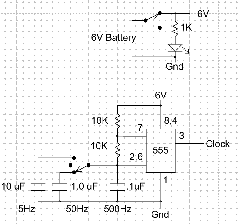
This is the wiring of the 555 timer and the power switch. Either use 6 volts or add a 5 volt regulator to protect your BOB (Break out Board) from the excessive voltages. I was using an old battery that was only putting out about 6 volts. You might also be able to tap into 5 volts from your CNC.
Here is a link to a video of the homemade CNC and this pendant working. This video was from before the 555 was put inside of the pendant. http://youtu.be/nbSun9bJMPo
Here is what the DIY CNC looks like today.
Here is the latest video on YouTube: http://youtu.be/YB4Aem0amOo
Here is what the insides of the CNC Pendant look like. The 555 is on the left side and the 9 volt battery is only safe to use if all of your CNC inputs have opti-couplers. The cable is a 4 pair network cable.
This is the schematic diagram of the wiring of the direction switches. You need either 6 Volts or you can use 9 volts and a 5 volt regulator.
This is the wiring of the 555 timer and the power switch. Either use 6 volts or add a 5 volt regulator to protect your BOB (Break out Board) from the excessive voltages. I was using an old battery that was only putting out about 6 volts. You might also be able to tap into 5 volts from your CNC.
Here is what the DIY CNC looks like today.
Here is the latest video on YouTube: http://youtu.be/YB4Aem0amOo
Subscribe to:
Comments (Atom)


