Once again I am fixing one of my two Fresh AIr by ecoQuest air filters. This time it struggles to turn on. I was taking longer and longer to start up making multiple attempts but then failing and trying again. It acted like a bad capacitor and the 8 volt power was at 5 volts so I tried a 220uF 16 volt capacitor from the 8 volts to ground. It made no difference. Then I moved the positive lead to the 12 volt power supply and it WORKED!
These pictures show where I soldered in the capacitor. It need a little glue under it as well.
I found myself once again doing some EcoQuest Fresh Air II air purifier repairs. One of ours quit making ozone. I opened it up but could not find the problem. After looking at it several times and getting ready to salvage parts and toss it, I then discovered that R11 was toast. Checking the FET, a 10N20L showed that it was shorted!
I disconnected the 10N20L by clipping the leads and it was still shorted. R11 was toast and there was no way to find out its value. Unfortunatly I threw out my spare board! Oops.
I could not find a 10N20 but did find a IRF630 that has similar specs and used that. The drain is connected by the case but the replacement will not solder to the board so you will need to run a small jumper wire. A 4.7 ohm one watt resistor will work for R11 as it was a current limiter resistor (I think).
So it has been up and running for a couple of hours now with no problems.
Aliexpress kept saying my package arrived but was not deliverable, there was a "Delivery Issue". This went on for three or four days. So I went to the post office and asked. They asked for my address and said there was no package for me. The clerk also advised me that several others have also asked for packages from AliExpress. I was told that it was a scam.
I went back again the next day and asked if they ahd a package that was not deliverable because the adress was missing. Sure enough, there was my package. What AliExpress does is send the package from China to Kentucky where it is then sent to the purchaser. However, there is something wrong with their addressing that the address is not complete!
This is what the second shipping label looks like. As you cna see the adedress is not complete. I do not know how to fix this but someone needs to cntact them and fix the problem. Otherwise everyone is going to think they are a scam! Also there is no way to get the second tracking number to see it is stuck at the post office.
I purchased a Sony BPD-S1500 Blue Ray DVD player because I had accidently bought a Blue-Ray DVD. After about a year of occasional use, it stopped working. The symptoms were that the logo would show up, then the screen would flash blue, then nothing. The DVD tray would still open and close but there was nothing on the screen. It looked exactly like a Raspberry Pi trying to run on a lame power supply. I opened up the case and discovered four pads next to the power jack. These would normally be used for power filter capacitors to help stabilize the power. The front two pads are power and the back two are ground. I added a 100uF 25 volt capacitor to the pads.
The unused pads are circled in red in this picture.
Here is the capacitor I added, the leads should have been cut shorter.
Sure enough this simple repair fixed the DVD player. I am watching a movie while I write this!
I recently built a BH1417 FM Transmitter Kit found on eBay. Here is the eBay advertisement:
There is another web site with instructions at: https://goughlui.com/2016/10/27/project-yydzw-bh1417f-based-stereo-fm-transmitter-kit/
This is a list of the components. This List does not include the semiconductors, and the coils L1 is a RFC, L2 and L3 are small coils of enameled wire. There are also two jumper wires that you cna make out of the clipped off resistor leads.
I started by soldering the surface mount components that are mounted to the bottom of the board. The IC soldered very easily using a fine soldering tip. The traces are far enough apart that they do not tend to bridge with solder.
Next I soldered the small disc capacitors on the top side of the board. Soldering the resistors would have likely been better thing to do first.
This shows the board almost complete. Some of the electrolyte capacitors were 50 volt models and hence they were to big but I made them fit anyway.
This is what the switch settings are:
This shows where the components go on the board.
This shows where the surface mount components go on the bottom of the board.
This is my NanoVNA Vector Network Analyzer 50KHz-900MHz with 2.8" LCD Screen Review. To start with I am used to using a big expensive Agilent RF VNA. I thought a pocket sized model would be great for hamfests and stuff like that. So I bought one on eBay. I was very disappointed. After an hour of trying to set it up to 150 MHz spanning 10 MHz I gave up! The selection switch makes it unusable. Maybe mine was just defective? This is what the screen looks like when turned on and off..
This is what the guts look like with the back cover and the battery removed. Note the pads for a SD memory adapter. Some way to save settings would have been nice.
What I do not like about this device is this switch. It has so frustrated me that I am almost ready to get rid of it. Should I buy a better switch or just sell the device? It hangs in one direction and the pressure to move it side to side often results in a key selected response. Sometime I just gave up and powered off and back on to try setting it up again. This switch is a disaster!
This is what it looks like with the top cover removed and the LCD screen moved out of the way.
I recently took apart a Ionic foot bath controller to try to silence the beeper. It beeps far too much saying the current is not correct. It actually says "Add Water".
First of all you can dissemble the array. It NEEDS to be cleaned after every use. If not stuff builds up on it and it becomes unusable.
This is what the controller looks like with the cover removed.
This is the back side of the control panel.
Here is the power supply.
The controllers weight comes from this big power transformer.
This is a picture of the front side of the controller.
i changed a resistor value in the controller driver circuit for the beeper. It had no effect.
I purchased a Teensy 3.1 and Smart Matrix SD with 32x32 LED panel kit. It is called "Pixelmatix SmartMatrix SD Shield KIT, Teensy 3.1, 32x32 RGB LED matrix 4mm pitch". It had some bugs like the connector that goes to the LED panel, if installed on the Smart Matrix shield, would not fit the panel that came with the kit. The power connector was in the way. So as a solution I used a ribbon cable from the smart matrix to the LED panel. I also added female headers so that the Teensy processor can be removed and used elsewhere.
Here is a video of it working.
This is a close up of the Teensy and SmartMatrix shield. Note that everything is on the top side of the board.
Now to fix the Teensy code to support the newer 64x32 LED panels.
Here is a video of the Teensy working with two 64x32 LED panels after being "Reset" with the code below.
This is the reset code.
// SMart Matrix Panel Reset Program
// For use with newer LED Panels
// Written 3/28/2019 by Bob Davis
int MaxLed = 256;
I am building a Chinese RTL-SDR Kit. To start with I was trained in soldering by MERP (Miniature Electronics Repair) school in the US Navy. I was taught NASA standards for soldering. They will surely disown me after seeing these pictures of my soldering. This kit is NOT easy! I also work for a communications company. I have built all kinds of communications equipment including surface mounted parts and hand wound coils.
Here is what the kit parts look like. There are many really tiny parts in the parts bag!
The circuit board comes with none of the surface mount parts installed.
To solder the surface mounted parts you will need a magnifying headband visor. You will also need tweezers and a really fine soldering tip. Apply a small amount of solder to one pad and place one end of the part in the molten solder. Then solder the other end. Then clean up the first side. The surface mount parts are marked except for the 222 resistors, the LED and the 4.7uH choke. The LED is in a black part holder and has a green stripe. There are extras of some parts in case you loose some.
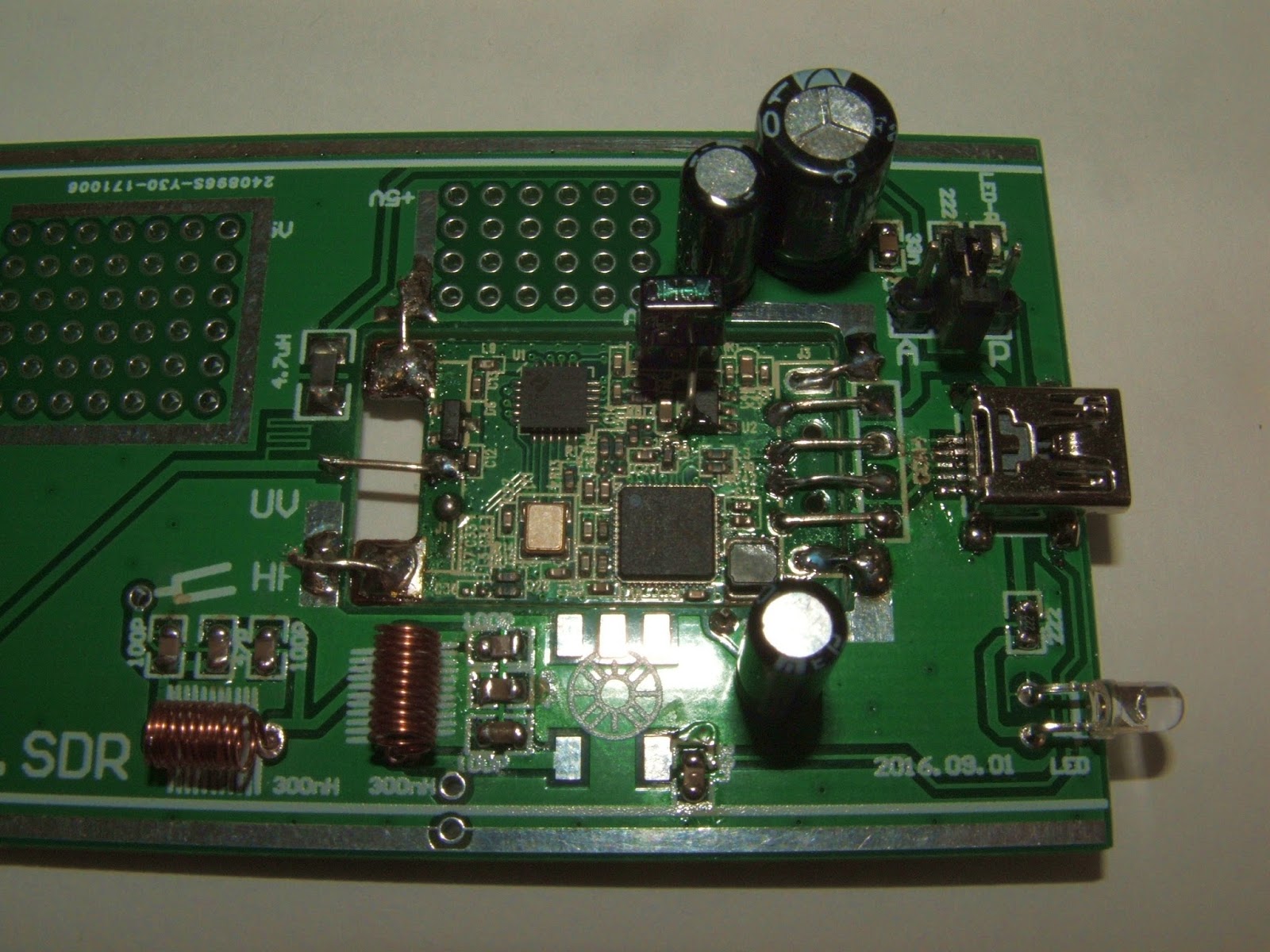
Here is a picture of the circuit board with the surface mounted parts jacks, and capacitors added. The green stripe of the LED goes towards the USB jack. The USB Jack is really hard to solder. I ended up with a solder bridge. After trying every trick to get rid of the bridge I resorted to using solder wick to soak up the extra solder. The capacitors should have their ground stripes facing the outer edges of the board.
I skipped adding the coils and went right to the disassembling USB dongle. Use solder wick to remove the solder on the ground connections. Then clip off the four USB jack pins using flush cutters. Then clear the metal out of the holes with a solder sucker. (Or heat and tap).
To add the USB assembly make two jumper hooks out of the former capacitor wires. Use them to hold the USB assembly up as in the following picture. Then solder them in place on both the top and bottom sides.
Next make a |_____| to connect the bottom grounds together as in the next picture.
Then add the four USB jumpers (from the old USB jack holes to the new jacks holes), two ground jumpers, and the RF input jumper on the top side of the board.
There is a jumper to add to the bottom of the board. It runs from one of the pins of a five pin device (likely a voltage regulator) to the edge.
It is easiest to attach the jumper just to the lower side of one of the pins as seen in this next illustration.
Then there is also an extra jumper to run on the top side. It also runs from one of the pins of a five pin device to the edge. It runs underneath the IR receiver, unless you have removed the IR (Remote Control) receiver.
There are two small coils to wind. The specs say 11 turns on a 3mm (.118") drill bit. From other peoples pictures it looks like some people are using a .125 (1/8 inch) drill bit instead.
Here it what it looks like with those coils installed.
Next is the beginning of the hardest part. Making and installing the 25 MHz coil. First the wire was all one color. That will require a voltmeter to figure out. Second it was one wire. You will need three lengths of wire about one foot each. You can mark the ends with colors with a permanent marker if you do not have a meter. Twist the three wires together to form one three conductor wire. You might need a needle to thread it through the ferrite bead 9 times.
Next label and meter the wires. You will have to tin them first to get through the enamel.
Twist the Y* and R wires together and solder it to the circuit board. You should have Y then Y*R then R*. Then cut off the B leads and the two that are twisted together.
I just purchased a SainSmart DDS140 DSO on eBay. So far I have figured out how to get a trace on the screen using the built in signal generator. Who puts the "Start" button in the bottom right corner? Next is to test it in some real world situations like my WS2812 LED strip signs.
This is the built in 1 KHz test signal.
This is the "0" bit for my WS2812 signs. It is .19 us, it is supposed to be about .400 us.
This is the "1" bit for my WS2812 signs. It is .57 us, it is supposed to be about .800 us. I had to measure from the center line as the trigger had issues with the lower signal level. In fact I had to write a version of the sign software that sent all 1's to be able to capture the pulses.