I purchased a DigitNow! Video Capture Device to use as a P2 card alternative. It works at 720P with a Panasonic AG-HVX200 Camera. You have to select the input every time you turn it on. It has built in RCA jacks that makes connection it to the camera easier and more reliable. It also has a wired remote "Record" Button. It costs about the same as a Panasonic P2 card but can work with any USB memory stick.
Here is the video recorded on the DigitNow! recorder.
Here are front and back views of the DigitNow! video recorder.
Showing posts with label Camera Repair. Show all posts
Monday, December 23, 2019
Thursday, October 3, 2019
Panasonic AG-HVX200 Recorder with AGPTEK VG0020 P2 card alternative
I found a better way to record video from a Panasonic AG-HVX200 video camera. For the price of one Panasonic P2 memory card you can buy an interface that records in 720P to a memory stick or to an external hard drive. It is the AGPTEK VG0020. The adapter also has a HDMI output that you can connect to a bigger monitor.
I first tried the VG0020 at 1080i video from the camera. It would not work with one monitor and with another monitor it had a noise bar wandering through the picture. When I switched the camera to 720p the picture cleared up and it works with all the monitors that I have tried.
Here is a picture of the AGPTEK VG0200 setup.
The Video comes out of the component output via an adapter cable. Audio is from the RCA audio in/out jacks.
Here is the video. The audio level is a little low..
I first tried the VG0020 at 1080i video from the camera. It would not work with one monitor and with another monitor it had a noise bar wandering through the picture. When I switched the camera to 720p the picture cleared up and it works with all the monitors that I have tried.
Here is a picture of the AGPTEK VG0200 setup.
The Video comes out of the component output via an adapter cable. Audio is from the RCA audio in/out jacks.
Here is the video. The audio level is a little low..
Tuesday, September 17, 2019
Panasonic AG-HVX200 to HDMI setup.
I have finally managed to connect a HVX200 camera to an HDMI monitor. The secret is to use a YPBPR to HDMI converter. You will also need a special connector to three RCA plug cable assembly. The converter does not work with all monitors, so far 2 out of 3 monitors work with it.
Here is the eBay ad for the needed cable, make sure you get a male D Terminal connector.
This is a close-up of the cable from the ad.
This is where the connector connects to the camera. You can go into the video in/out settings and select 1080i for the highest possible resolution.
Next up is to test a HDMI to USB converter/video capture adapter.
Thursday, June 27, 2019
Panasonic AG HVX200 Video Camera Repair when buttons do not work
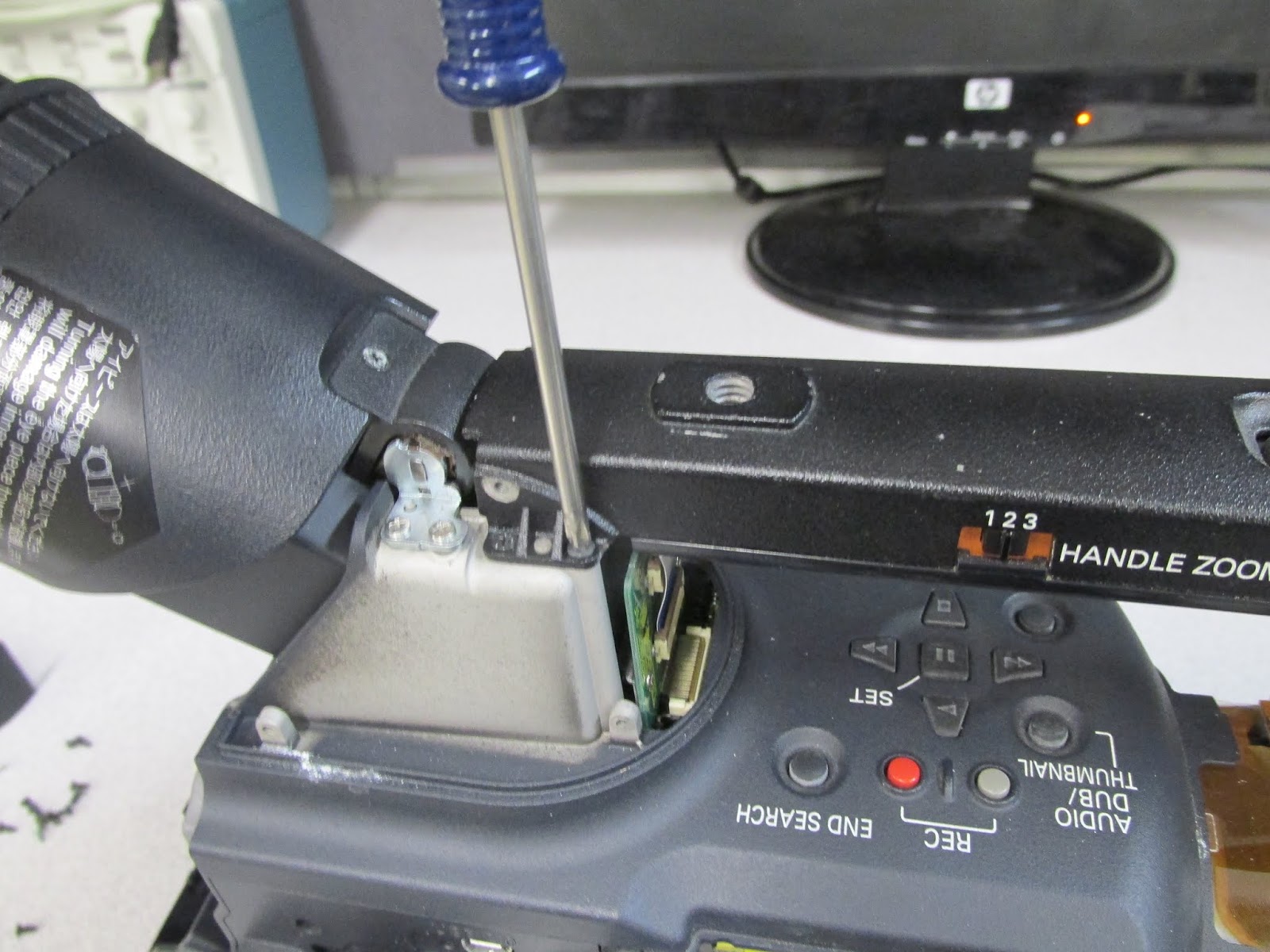
I purchased a Panasonic HVX200 video camera really cheap on eBay. It was missing many screws the buttons did not work and the power was always on. There were some stripped screws where someone had tried to take it apart. The cure is to reset the ribbon cables. First of all there is a great tutorial on how to dissemble it at:
http://www.dvxuser.com/V6/showthread.php?177130-HVX200P-Modular-Disassembly-(DIY-Photos)-To-Be-Cont
Next what you need to do is re-seat the ribbon cables on the top board. Then sure enough it powers on and off and the buttons work just fine! The ribbon cables to re-seat are white with a blue stripe in the picture below.
This picture shows the crud on one of the ribbon connectors. (Zoom in to see it better)
The final results - lots of parts!
http://www.dvxuser.com/V6/showthread.php?177130-HVX200P-Modular-Disassembly-(DIY-Photos)-To-Be-Cont
Next what you need to do is re-seat the ribbon cables on the top board. Then sure enough it powers on and off and the buttons work just fine! The ribbon cables to re-seat are white with a blue stripe in the picture below.
This picture shows the crud on one of the ribbon connectors. (Zoom in to see it better)
Here are my pictures of dissembling the camera.
The final results - lots of parts!
Wednesday, May 1, 2019
Panasonic Pro AG-DVC7 Rebuild with higher resolution
I am rebuilding a Panasonic AG-DVC7 to give a better image resolution. I am looking at USB Camera boards with sound on eBay to attach to the existing optics. An Arduino will handle the Zoom, Focus, and Iris. A Raspberry Pi will do the recording and provide a viewfinder.
One of the first steps is to reverse engineer the optics.
This is the main side of the optical assembly with the Zoom and Focus stepper motors.
This is the back side - The Iris solenoid connections are shown. You need to remove the cover on the left to get to the connections.
This is a close up of the Iris assembly. You do not need to take the optics apart this far.
Here is the first video of the arrangement working.
Yet to do:
Increase the range of the zoom - Add a spacer between board and the image sensor.
Set up a viewfinder - Need a small 5-7 inch HDMI Monitor.
Make the steps finer/smoother. - Done with 8 phases for servos instead of 4.
Auto focus - Need to run the focus to its stop then keep track of its position.
Perhaps add an ultrasonic distance sensor?
Focus Issue - Somehow I damaged the optical assembly, it does not focus properly when installed back in the DVC7 camera....
Here is the schematic of the Arduino servo controller that was used for the camera.
This is a close up of the Arduino and servo driver interface.
This is a close up of the Raspberry Pi. You could use a USB camera board as well.
Here is the code for the servos.
/*****************************
Dual Four wire stepper motor Control
For Panasonic AG-DVC7 with two servos
by Bob Davis
May 1, 2019
*****************************/
// To L293 one
int motor1A =4;
int motor1B =5;
int motor1C =6;
int motor1D =7;
// To L293 Two
int motor2A =8;
int motor2B =9;
int motor2C =10;
int motor2D =11;
// 2P Momentary Switch One Center is off
int m1sw1 = 14;
int m1sw2 = 15;
// 2P Momentary Switch Two Center is off
int m2sw1 = 16;
int m2sw2 = 17;
// Variables
int m1step = 0;
int m2step = 0;
int mspeed = 100; // Step speed
void setup() {
pinMode(motor1A, OUTPUT);
pinMode(motor1B, OUTPUT);
pinMode(motor1C, OUTPUT);
pinMode(motor1D, OUTPUT);
pinMode(motor2A, OUTPUT);
pinMode(motor2B, OUTPUT);
pinMode(motor2C, OUTPUT);
pinMode(motor2D, OUTPUT);
pinMode(m1sw1, INPUT_PULLUP);
pinMode(m1sw2, INPUT_PULLUP);
pinMode(m2sw1, INPUT_PULLUP);
pinMode(m2sw2, INPUT_PULLUP);
}
void loop() {
// read switches
if (digitalRead (m1sw1)==HIGH) m1step=m1step+1;
if (digitalRead (m1sw2)==HIGH) m1step=m1step-1;
if (m1step > 7) m1step=0;
if (m1step < 0) m1step=7;
if (digitalRead (m2sw1)==HIGH) m2step=m2step+1;
if (digitalRead (m2sw2)==HIGH) m2step=m2step-1;
if (m2step > 7) m2step=0;
if (m2step < 0) m2step=7;
// respond M1 with 8 smooth steps
if (m1step==0){
digitalWrite (motor1A, LOW); //+A
digitalWrite (motor1B, HIGH);
digitalWrite (motor1C, HIGH);
digitalWrite (motor1D, HIGH);}
if (m1step==1){
digitalWrite (motor1A, LOW); //+A,+B
digitalWrite (motor1B, HIGH);
digitalWrite (motor1C, LOW);
digitalWrite (motor1D, HIGH);}
if (m1step==2){
digitalWrite (motor1A, HIGH); //+B
digitalWrite (motor1B, HIGH);
digitalWrite (motor1C, LOW);
digitalWrite (motor1D, HIGH);}
if (m1step==3){
digitalWrite (motor1A, HIGH); //+B,-A
digitalWrite (motor1B, LOW);
digitalWrite (motor1C, LOW);
digitalWrite (motor1D, HIGH);}
if (m1step==4){
digitalWrite (motor1A, HIGH); // -A
digitalWrite (motor1B, LOW);
digitalWrite (motor1C, HIGH);
digitalWrite (motor1D, HIGH);}
if (m1step==5){
digitalWrite (motor1A, HIGH); // -A,-B
digitalWrite (motor1B, LOW);
digitalWrite (motor1C, HIGH);
digitalWrite (motor1D, LOW);}
if (m1step==6){
digitalWrite (motor1A, HIGH); // -B
digitalWrite (motor1B, HIGH);
digitalWrite (motor1C, HIGH);
digitalWrite (motor1D, LOW);}
if (m1step==7){
digitalWrite (motor1A, LOW); // -B,+A
digitalWrite (motor1B, HIGH);
digitalWrite (motor1C, HIGH);
digitalWrite (motor1D, LOW);}
// respond M2
if (m2step==0){
digitalWrite (motor2A, LOW); //+A
digitalWrite (motor2B, HIGH);
digitalWrite (motor2C, HIGH);
digitalWrite (motor2D, HIGH);}
if (m2step==1){
digitalWrite (motor2A, LOW); //+A,+B
digitalWrite (motor2B, HIGH);
digitalWrite (motor2C, LOW);
digitalWrite (motor2D, HIGH);}
if (m2step==2){
digitalWrite (motor2A, HIGH); //+B
digitalWrite (motor2B, HIGH);
digitalWrite (motor2C, LOW);
digitalWrite (motor2D, HIGH);}
if (m2step==3){
digitalWrite (motor2A, HIGH); //+B,-A
digitalWrite (motor2B, LOW);
digitalWrite (motor2C, LOW);
digitalWrite (motor2D, HIGH);}
if (m2step==4){
digitalWrite (motor2A, HIGH); // -A
digitalWrite (motor2B, LOW);
digitalWrite (motor2C, HIGH);
digitalWrite (motor2D, HIGH);}
if (m2step==5){
digitalWrite (motor2A, HIGH); // -A,-B
digitalWrite (motor2B, LOW);
digitalWrite (motor2C, HIGH);
digitalWrite (motor2D, LOW);}
if (m2step==6){
digitalWrite (motor2A, HIGH); // -B
digitalWrite (motor2B, HIGH);
digitalWrite (motor2C, HIGH);
digitalWrite (motor2D, LOW);}
if (m2step==7){
digitalWrite (motor2A, LOW); // -B,+A
digitalWrite (motor2B, HIGH);
digitalWrite (motor2C, HIGH);
digitalWrite (motor2D, LOW);}
delay (mspeed);
}
One of the first steps is to reverse engineer the optics.
This is the main side of the optical assembly with the Zoom and Focus stepper motors.
This is the back side - The Iris solenoid connections are shown. You need to remove the cover on the left to get to the connections.
This is a close up of the Iris assembly. You do not need to take the optics apart this far.
Here is the first video of the arrangement working.
Yet to do:
Increase the range of the zoom - Add a spacer between board and the image sensor.
Set up a viewfinder - Need a small 5-7 inch HDMI Monitor.
Make the steps finer/smoother. - Done with 8 phases for servos instead of 4.
Auto focus - Need to run the focus to its stop then keep track of its position.
Perhaps add an ultrasonic distance sensor?
Focus Issue - Somehow I damaged the optical assembly, it does not focus properly when installed back in the DVC7 camera....
Here is the schematic of the Arduino servo controller that was used for the camera.
This is a close up of the Arduino and servo driver interface.
This is a close up of the Raspberry Pi. You could use a USB camera board as well.
Here is the code for the servos.
/*****************************
Dual Four wire stepper motor Control
For Panasonic AG-DVC7 with two servos
by Bob Davis
May 1, 2019
*****************************/
// To L293 one
int motor1A =4;
int motor1B =5;
int motor1C =6;
int motor1D =7;
// To L293 Two
int motor2A =8;
int motor2B =9;
int motor2C =10;
int motor2D =11;
// 2P Momentary Switch One Center is off
int m1sw1 = 14;
int m1sw2 = 15;
// 2P Momentary Switch Two Center is off
int m2sw1 = 16;
int m2sw2 = 17;
// Variables
int m1step = 0;
int m2step = 0;
int mspeed = 100; // Step speed
void setup() {
pinMode(motor1A, OUTPUT);
pinMode(motor1B, OUTPUT);
pinMode(motor1C, OUTPUT);
pinMode(motor1D, OUTPUT);
pinMode(motor2A, OUTPUT);
pinMode(motor2B, OUTPUT);
pinMode(motor2C, OUTPUT);
pinMode(motor2D, OUTPUT);
pinMode(m1sw1, INPUT_PULLUP);
pinMode(m1sw2, INPUT_PULLUP);
pinMode(m2sw1, INPUT_PULLUP);
pinMode(m2sw2, INPUT_PULLUP);
}
void loop() {
// read switches
if (digitalRead (m1sw1)==HIGH) m1step=m1step+1;
if (digitalRead (m1sw2)==HIGH) m1step=m1step-1;
if (m1step > 7) m1step=0;
if (m1step < 0) m1step=7;
if (digitalRead (m2sw1)==HIGH) m2step=m2step+1;
if (digitalRead (m2sw2)==HIGH) m2step=m2step-1;
if (m2step > 7) m2step=0;
if (m2step < 0) m2step=7;
// respond M1 with 8 smooth steps
if (m1step==0){
digitalWrite (motor1A, LOW); //+A
digitalWrite (motor1B, HIGH);
digitalWrite (motor1C, HIGH);
digitalWrite (motor1D, HIGH);}
if (m1step==1){
digitalWrite (motor1A, LOW); //+A,+B
digitalWrite (motor1B, HIGH);
digitalWrite (motor1C, LOW);
digitalWrite (motor1D, HIGH);}
if (m1step==2){
digitalWrite (motor1A, HIGH); //+B
digitalWrite (motor1B, HIGH);
digitalWrite (motor1C, LOW);
digitalWrite (motor1D, HIGH);}
if (m1step==3){
digitalWrite (motor1A, HIGH); //+B,-A
digitalWrite (motor1B, LOW);
digitalWrite (motor1C, LOW);
digitalWrite (motor1D, HIGH);}
if (m1step==4){
digitalWrite (motor1A, HIGH); // -A
digitalWrite (motor1B, LOW);
digitalWrite (motor1C, HIGH);
digitalWrite (motor1D, HIGH);}
if (m1step==5){
digitalWrite (motor1A, HIGH); // -A,-B
digitalWrite (motor1B, LOW);
digitalWrite (motor1C, HIGH);
digitalWrite (motor1D, LOW);}
if (m1step==6){
digitalWrite (motor1A, HIGH); // -B
digitalWrite (motor1B, HIGH);
digitalWrite (motor1C, HIGH);
digitalWrite (motor1D, LOW);}
if (m1step==7){
digitalWrite (motor1A, LOW); // -B,+A
digitalWrite (motor1B, HIGH);
digitalWrite (motor1C, HIGH);
digitalWrite (motor1D, LOW);}
// respond M2
if (m2step==0){
digitalWrite (motor2A, LOW); //+A
digitalWrite (motor2B, HIGH);
digitalWrite (motor2C, HIGH);
digitalWrite (motor2D, HIGH);}
if (m2step==1){
digitalWrite (motor2A, LOW); //+A,+B
digitalWrite (motor2B, HIGH);
digitalWrite (motor2C, LOW);
digitalWrite (motor2D, HIGH);}
if (m2step==2){
digitalWrite (motor2A, HIGH); //+B
digitalWrite (motor2B, HIGH);
digitalWrite (motor2C, LOW);
digitalWrite (motor2D, HIGH);}
if (m2step==3){
digitalWrite (motor2A, HIGH); //+B,-A
digitalWrite (motor2B, LOW);
digitalWrite (motor2C, LOW);
digitalWrite (motor2D, HIGH);}
if (m2step==4){
digitalWrite (motor2A, HIGH); // -A
digitalWrite (motor2B, LOW);
digitalWrite (motor2C, HIGH);
digitalWrite (motor2D, HIGH);}
if (m2step==5){
digitalWrite (motor2A, HIGH); // -A,-B
digitalWrite (motor2B, LOW);
digitalWrite (motor2C, HIGH);
digitalWrite (motor2D, LOW);}
if (m2step==6){
digitalWrite (motor2A, HIGH); // -B
digitalWrite (motor2B, HIGH);
digitalWrite (motor2C, HIGH);
digitalWrite (motor2D, LOW);}
if (m2step==7){
digitalWrite (motor2A, LOW); // -B,+A
digitalWrite (motor2B, HIGH);
digitalWrite (motor2C, HIGH);
digitalWrite (motor2D, LOW);}
delay (mspeed);
}
Monday, April 29, 2019
HP Laptop Camera to USB Webcam Conversion
I have been working on hacking a Panasonic DVX100 camera. They sell for about $100 used but they were $4000 new. They still contain about $1000 of optics. So I thought about using a different cameras electronics and mating it with the optics. Then I was further sidetracked by the idea of using an old laptop camera as a USB camera.
I salvaged two laptop cameras from old laptops. One was just 640x480 resolution but the other was 1280x960! However the lens was glued in place making using it with the better optics not possible. Here is a picture of the better camera.
Then, to hack the interface, the ground was metered to connect to the green wire. Red was power and the twisted pair was the data pair. I guessed on the twisted pair and got it right the first time. I added heat shrink tubing later on.
Camera Green - USB Black
Camera Red - USB Red
Camera Black - USB Green
Camera Blue - USB White.
Here are the test results from https://webcamtests.com/
I salvaged two laptop cameras from old laptops. One was just 640x480 resolution but the other was 1280x960! However the lens was glued in place making using it with the better optics not possible. Here is a picture of the better camera.
Then, to hack the interface, the ground was metered to connect to the green wire. Red was power and the twisted pair was the data pair. I guessed on the twisted pair and got it right the first time. I added heat shrink tubing later on.
Camera Green - USB Black
Camera Red - USB Red
Camera Black - USB Green
Camera Blue - USB White.
Here are the test results from https://webcamtests.com/
And finally a picture of me taken with the better camera:
Thursday, April 11, 2019
Panasonic DVX100 Video camera repair and modification
This started with a dream that I had three professional cameras. At one time I had two Panasonic AG-DVC7 cameras. My brother had them, so I asked if I could have them back. He was happy to return them because they were both very difficult to turn on. I have shown how to repair that problem in another blog post. However, my research showed that the DVX100 that once cost about $4000 was now available on eBay for about $50 each needing repairs.
The DVX100 has a actual native resolution of 1546 x 990 according to some sources. At one time there was the a modification to take advantage of this higher resolution. I think that I might be the ideal person to revive this modification since I have lots of experience in modifying everything from LED sighs to computer monitors.
I bought two of the cameras for $85 that were in need of repair. To my surprise they both worked! Even the tape decks could record and play back videos. They are missing some parts and one of the LCD screens goes crazy when you move it.
This is what the insides of the camera look like. You have to remove the top microphone assembly to get to a screw under it as well as the bottom plate to get to three screws under that.
This is the LCD side cover. There are a lot of connectors to unplug including two that are under the microphone assembly.
This is the top of the video processor board.
This is the bottom of the video processor board. Note the two VSP2212 video processor and analog to digital converter chips on the left side. The third one is located on the top of the board.
This is the image stabilization mechanism. Two coils one for X and one for Y move inside of magnets.
This is the iris solenoid (A screwdriver is holding it open) with the filters also visible on the right side.
The DVX100 has a actual native resolution of 1546 x 990 according to some sources. At one time there was the a modification to take advantage of this higher resolution. I think that I might be the ideal person to revive this modification since I have lots of experience in modifying everything from LED sighs to computer monitors.
I bought two of the cameras for $85 that were in need of repair. To my surprise they both worked! Even the tape decks could record and play back videos. They are missing some parts and one of the LCD screens goes crazy when you move it.
| DVX100 Cover Removed |
This is the LCD side cover. There are a lot of connectors to unplug including two that are under the microphone assembly.
This is the top of the video processor board.
This is the bottom of the video processor board. Note the two VSP2212 video processor and analog to digital converter chips on the left side. The third one is located on the top of the board.
Here is the block diagram of the video processor.
Here is the pin numbers to connect to.
The problem now is what do I connect to? If I connect to the analog input then I need to have a circuit to process the CMOS output, that is not straight analog, but instead it is clock pulses followed by analog values. I also loose the gain control circuitry (PGA). If I connect to the digital outputs I have to connect 12 wires to each analog converter and I am limited to the sampling rate of the converter that has a maximum clock of 20 MHz or 1,500 pixels horizontally. That is assuming that they clocked it at the maximum frequency (highly unlikely).
These pictures compare the optics of the DVC7 to the DVX100 optics.
![]() |
| DVX100 Lens |
These next two pictures compare images between the two cameras, the DVC7 is first.
This might freak you out, but I disassembled the optics! Its from a slightly broken camera so you can breath a sigh of relief.
This is the focus assembly (No wonder there is no focus motor). There are two coils attached to the lens that then move inside of a top and bottom magnet. This is much like a hard rive positioning mechanism.
| DVX100 Focus |
This is the image stabilization mechanism. Two coils one for X and one for Y move inside of magnets.
| DVX100 Stabilization |
This is the iris solenoid (A screwdriver is holding it open) with the filters also visible on the right side.
| DVX100 Iris |
Here is how to connect to the optical assembly. The zoom motor is a conventional motor, connect power one way to zoom in and reverse it to zoom out. The Iris solenoid needs just two pins as marked. The focus coils (just two connections) only need a little power to move. The other connections next to the focus coils are for the manual zoom/focus ring that is missing on this lens assembly. Varying the voltage varies the focus lens position.
There are three optical sensors, one is for the filters. There is a variable resistor to sense the position of the zoom. The image stabilizer might be the hardest thing to operate. I can see the image is off center when power is not applied. That lens is what you hear rattling inside the lens assembly. Hopefully I can break it down to two coils that need to be energized.
Subscribe to:
Posts (Atom)