Showing posts with label LCD. Show all posts

Saturday, February 3, 2024

The Capacitor Disaster is back!

 About 20 years ago the market was flooded with faulty capacitors.  This is happening once again.  Three times within one week I had to fix things with bad capacitors.

The first one is a ONN Roku TV model 100012589.  The symptom was that ths screen goes blank but the sound keeps working.  When I removed the cover I could see the bulging leaking capacitors.


The next one is a internet repater.  It worked great for about 6 months then the power light became dim and it emitted a buzzing sound. I used two capacitors to fix this in the hopes that it would last longer this time.


The third one was a 5 volt power supply AC adapter.  I did not take any pictures.  Is anyone else seeing thes bad capacitors all too commonly once again?


Monday, July 10, 2023

I have damaged three TV's in a row while trying to fix them.

I am batting three in a row for destroying TV's while trying to fix them.  In all three cases all I had to do was replace the LED Backlights.  There was the 65" where I disconnected part of a ribbon cable to the screen.  Then there was a 55" when after taking it apart at least three times I laid it on its face to attach the back cover and somehow it ended up on its power cord that cracked the screen.  Now I have a 50" TV that I have damaged one of the SIDE ribbon cables.  I had them all tucked in but when I put on the bezel two of the side cables came out and were damaged by the bezel.

This picture shows the side ribbon cables (The screen is on its other side).  The cables loop around and are only about 3/8" long.  They tuck into spaces that are alloted for them.


The result of the damage is the top left side of the screen is out.  If I play with the damaged ribon cable it starts working for a few minutes.


The 65" TV that I accidently disconnected part of a ribbon cable, then fixed it with a clip, is still working!


Tuesday, June 13, 2023

CA-300V Super LED tester TV Backlight Review

Years ago I started testing TV LED Backlights with 9 volt batteries.  There are even videos of me doing that on Youtube. Well I fianlly broke down and bought a LED tester.  The reason was that I had just received a second identical TV to one where I had replaced all of the LED strips and this time I did not want to buy any, but to reuse the good ones from the last TV instead.  But I was in for a big surprise.  Only two LEDs were bad in the last TV so I was sure I was all set to fix the new one.  However in the new TV there were at least 20 bad LED's.  Even with 8 good LED strips out of 10, I was still not able to fix all the lED's!!  The best I could do was to leave 2 bad LED's.  On top of that, as I reasembled the TV two lenses fell off of the strips, so it has to be taken back apart and repaired again!

The short story is that this tester works great.  I did have one strip that tested bad in the TV but tested good once it was removed for some reason.


Here is some of my LED strips that I have collected over the years that needed testing.
 
Here is how to test the LED strips.  Basically you go + to + on each strip.  Note that the strips are not always labeled correctly!  The - terminals are usually just shorts.  Trial and error is the quickest way to find the correct polarity.  You can use a jumper to short out one end of the LED strip if you want to go positive to negative at one end of the strip.  Once you replace the bad strips then test everything to make sure it works together before reasembling the TV.  Sometimes the LED strip connectors have issues.


This are some really burnt out LED's


The results are not that good!  A number of the lenses fell off and had to be glued back on.  It turns out that the lens has to be centered on the money or else you get uneven lighting. You can slso easily see where a LED is not working.  I guess I should have purchased new LED strips.....


I studied the "Lens Crooked" issue and what happens is that one of the three bumps slips off and the lens ends up higher on one side that the other, or off center.  This is quite common when you reglue the lens.  I do not know why so many of the lenses fell off the strips in this TV.  I suspect maybe it was dropped or something.  Also, I was reusing LED strips that had been removed form another TV, that process is known to loosen or even pop off the lenses.


I took it back apart and reglued three LED Lenses back in place.  Then, while putting it back together, I heard another lens fall off.  Then I took it apart again and found not one, but three lenses had fallen off.  None of the loose lenses had been glued on before.  So I glued them and put it back together again.  The bad LED is on an "A" strip and I only have "B" strips that are spare.  Overall it looks much better but still is not perfect.  The only real solution is to replace all the LED strips with new ones....

Monday, June 5, 2023

Dynex DX-37L150A11 Replace Fluorescent Backlight tubes with LED strips

I hate to see newer TV's go in the garbage.  Recently I was at our local firehall as they filled bin after bin with defective TV's as part of our towns cleanup.  Many, if not most TV's were just having issues with the backlighting.  I even brought a 55" model home to repair.  Anyway, I had a 37" TV that had the older fluorescent tubes for backlighting.  I watched as one, then two, then three of the tubes went out.  Then the TV quit, no backlight.  So I thought I would fix it with LED strips just for the fun of it.

At first I tried RGBW LED's because I had them on hand.  They did not work well at all.  Amoung other issues some of them came loose and fell against the screen becoming very visable.


Then I used some 12 volt LED strips.  I added glue to make sure they stayed in place as well as stuffing the LED strip ends under the plastic edges at both ends.  Total cost $18 for the LED strips.


Putting the TV back together...


This is the old fluorescent tube driver circuit board and the 10 tubes that were removed from the TV set in the upgrade process.


This is the almost final result.  Unfortunatly one of the LED strips developed issues.  I think one of the wires shorted to the metal chassis and maybe burnt out some LED's.  The strips were 12 volt strips and the power to the removed tube driver was 24 volts, so I have arranged the strings in sets of two strips in series. Now to take the TV apart for a third time and replace the defective LED strip!


Update: I replaced the bad LED strip and now it works perfectly!

Thursday, May 25, 2023

E4SW6518RKU 65 inch TV Repair LED Backlights

I recently fixed a E4SW6518RKU 65 inch TV by replacing the LED Backlights.  The TV is so huge that there was almost not enough room where I was working on it.  So I stacked everything behind it as I took them out so they would go back in in the same order.  The screen was attached to the black plastic pieces so I tokk them out together, but that makes it very difficult to put it back together.  Perhaps a knife would have seperated the screen from the black plastic parts.


The old LED strips are glued in.  You have to rock them side to side to get them out.  Even then they will be bent and the lens will pop off them..


One of the screen ribbon cables came apart so I used a clip to reattach it, but this does not seem reliable enough. Anyone have a better solution??


Wednesday, March 30, 2022

Dual 80x160 RGB LCD Robot eyes

My latest creation uses dual 80x160 RGB LCD's to produce two robot eyes.  They are wired together so they can not "wink".  On the other hand it only takes half of the code.  They are powered by an Arduino UNO.  I was going to do this with OLED's but someone sent me a LCD instead so I went with the LCD's.  Theoretically you can wire them to have different "CS" or chip selects so each eye would be independent.  I added some more circles.  There is a small white circle on the far left and right as well as a black circle that produces the ring around the blue of the eyes.

By the way these LCD's are five volt friendly and easily run off five volts as well as use five volt logic levels.

Here are a couple of pictures.  They are more blue in reality but the camera has issues with the blue.


Here is a video of them on YouTube.


Ideally you could have two channels of your 32 channel servo controller go to analog inputs of an Arduino to set the size and direction of the eyes.

Here is the code:
// Sample program for eyes on 80x160 TFT LCD Screen
// March 2022 by Bob Davis

#include <TFT.h>  // Arduino LCD library
#include <SPI.h>
 
// Pins
#define cs   10
#define dc   8
#define rst  9
// For Arduino Uno: MOSI = pin 11 and SCLK = pin 13.  
// Create an instance of the library
TFT TFTscreen = TFT(cs, dc, rst);

int width=160; 
void setup() {
 
   // Initialize the screen
   TFTscreen.begin();
   // Clear the screen
   TFTscreen.background(255,255,255);
   // Set font color to white
   TFTscreen.stroke(255,255,255);
   // Set the font size
   TFTscreen.setTextSize(2);
   // Write some text on the screen
//   TFTscreen.text("Hello World!",0,0);
}
 
void loop() {
   TFTscreen.background(255,255,255); // Clear Screen

   // Eyes Center  NOTE SCREEN IS UPSIDE DOWN 0,0=bottom right
   TFTscreen.fillCircle(25,65,15,0x0000);
   TFTscreen.fillCircle(135,65,15,0x0000); 
   TFTscreen.fillCircle(45,65,30,0x0000);
   TFTscreen.fillCircle(115,65,30,0x0000); 
   TFTscreen.fillRect(45,35,70,61,0x0000); // Connect Circles
   TFTscreen.fillCircle(80,65,35,0xFFFF);
   TFTscreen.fillCircle(80,65,30,0xFFE0);
   TFTscreen.fillCircle(80,65,10,0xFFFF);
   delay(1000);

   // Eyes Narrow
   TFTscreen.fill(255,255,255);
   TFTscreen.rect(0,30,160,20);
   TFTscreen.rect(0,78,160,21);
   delay(1000);

   // Eyes Right
//   TFTscreen.background(255,255,255);
   TFTscreen.fillCircle(25,65,15,0x0000);
   TFTscreen.fillCircle(135,65,15,0x0000); 
   TFTscreen.fillCircle(45,65,30,0x0000);
   TFTscreen.fillCircle(115,65,30,0x0000); 
   TFTscreen.fillRect(45,35,70,61,0x0000);// Connect Circles
   TFTscreen.fillCircle(110,65,35,0xFFFF);
   TFTscreen.fillCircle(110,65,30,0xFFE0);
   TFTscreen.fillCircle(110,65,10,0xFFFF);
   delay(1000);
   
   // Eyes Left
//   TFTscreen.background(255,255,255);
   TFTscreen.fillCircle(25,65,15,0x0000);
   TFTscreen.fillCircle(135,65,15,0x0000); 
   TFTscreen.fillCircle(45,65,30,0x0000);
   TFTscreen.fillCircle(115,65,30,0x0000); 
   TFTscreen.fillRect(45,35,70,61,0x0000);// Connect Circles
   TFTscreen.fillCircle(50,65,35,0xFFFF);
   TFTscreen.fillCircle(50,65,30,0xFFE0); // Blue
   TFTscreen.fillCircle(50,65,10,0xFFFF);
   delay(1000);
    
   // Eyes Big
   TFTscreen.fillCircle(25,65,15,0x0000);
   TFTscreen.fillCircle(135,65,15,0x0000); 
   TFTscreen.fillCircle(45,65,30,0x0000);
   TFTscreen.fillCircle(115,65,30,0x0000); 
   TFTscreen.fillCircle(60,65,40,0x0000);
   TFTscreen.fillCircle(100,65,40,0x0000); 
   TFTscreen.fillRect(65,25,40,81,0x0000); // Connect Circles
   TFTscreen.fillCircle(80,65,35,0xFFFF);
   TFTscreen.fillCircle(80,65,30,0xFFE0);
   TFTscreen.fillCircle(80,65,10,0xFFFF);
   delay(2000);
}

Monday, March 21, 2022

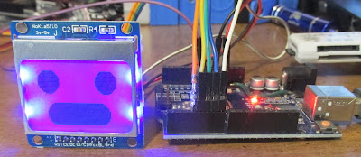
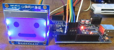
Nokia 5110 Robot Face Eyes and Mouth

 I thought I would try using a Nokia LCD for creating a face for my robot.  However I was greatly disappointed.  If you make his eyes white, then the border is also white.  So I had to make his eyes black.  The effect is not nearly as pronounced.  As a result I only created two expressions for this LCD.

Here is the two faces:


Here is the code for those two faces.

/*********************************************************************
Nokia 5110 LCD Robot Face
Many thankls to AdaFruit!
*********************************************************************/
#include <Adafruit_GFX.h>
#include <Adafruit_PCD8544.h>
// Software SPI (slower updates, more flexible pin options):
// pin 7 21- Serial clock out (SCLK)
// pin 6 20- Serial data out (DIN)
// pin 5 19- Data/Command select (D/C)
// pin 4 18- LCD chip select (CS)
// pin 3 17- LCD reset (RST)
//Adafruit_PCD8544 display = Adafruit_PCD8544(21, 20, 19, 18, 17);
Adafruit_PCD8544 display = Adafruit_PCD8544(7, 6, 5, 4, 3);
void setup()   {
  display.begin();
  display.setContrast(60);  // Default is 50
  display.clearDisplay();   // clears the screen and buffer
}
void loop() {
  // draw big eyes and mouth
  display.fillCircle(display.width()/6, display.height()/5, 10, BLACK);
  display.fillCircle(display.width()/6*5, display.height()/5, 10, BLACK);
  display.fillCircle(display.width()/4, display.height()-10, 10, BLACK);
  display.fillCircle(display.width()/4*3, display.height()-10, 10, BLACK);
  display.fillRect(display.width()/4, display.height()-20,display.width()/4*2,20, BLACK);
  display.display();
  delay(2000);
  display.clearDisplay();
  // draw eyes and mouth
  display.fillCircle(display.width()/6, display.height()/5, 7, BLACK);
  display.fillCircle(display.width()/6*5, display.height()/5, 7, BLACK);
  display.fillCircle(display.width()/4, display.height()-10, 5, BLACK);
  display.fillCircle(display.width()/4*3, display.height()-10, 5, BLACK);
  display.fillRect(display.width()/4, display.height()-14,display.width()/4*2,10,BLACK);
  display.display();
  delay(2000);
  display.clearDisplay();
}

Monday, March 7, 2022

Simple Arduino TFT LCD Robot eyes

I am working on making some better "eyes" for my humanoid robots. The 8x8 LED design was cool but I can do a lot more with an LCD screen.  I need to make it more universal to work with different sizes of screens.


This is a link to the video of this robot head being printed:

Here is the code so far:
// Program for Eyes on a 1.8" TFT LCD Screen

#include <TFT.h>  // Arduino LCD library
#include <SPI.h>
 
// Pins
#define cs   10
#define dc   9
#define rst  8
 
// Create an instance of the library
TFT TFTscreen = TFT(cs, dc, rst);
 
void setup() {
 
   // Initialize the screen
   TFTscreen.begin();
 
   // Clear the screen
   TFTscreen.background(0, 0, 0);
 
   // Set font color to white
   TFTscreen.stroke(255,255,255);
 
   // Set the font size
   TFTscreen.setTextSize(2);
 
   // Write some text on the screen
//   TFTscreen.text("Hello World!",0,0);
}
 
void loop() {
   TFTscreen.noStroke();
   // Eyes Center
   TFTscreen.fill(255,255,255);
   TFTscreen.circle(20,60,20);
   TFTscreen.circle(50,60,20); // oblong circle
   TFTscreen.rect(20,40,30,41);
   TFTscreen.fill(255,0,0);
   TFTscreen.circle(35,60,20);
   TFTscreen.fill(0,0,0);
   TFTscreen.circle(35,60,10);

   TFTscreen.fill(255,255,255);
   TFTscreen.circle(110,60,20);
   TFTscreen.circle(140,60,20);// oblong circle
   TFTscreen.rect(110,40,30,41);
   TFTscreen.fill(255,0,0);
   TFTscreen.circle(125,60,20);
   TFTscreen.fill(0,0,0);
   TFTscreen.circle(125,60,10);
   delay(1000);

   // Eyes Narrow
   TFTscreen.fill(0,0,0);
   TFTscreen.rect(0,40,160,10);
   TFTscreen.rect(0,70,160,11);
   delay(1000);
   
   // Eyes Big
   TFTscreen.fill(255,255,255);
   TFTscreen.circle(30,60,30);
   TFTscreen.circle(40,60,30); // oblong circle
   TFTscreen.rect(20,40,30,41);
   TFTscreen.fill(255,0,0);
   TFTscreen.circle(35,60,20);
   TFTscreen.fill(0,0,0);
   TFTscreen.circle(35,60,10);

   TFTscreen.fill(255,255,255);
   TFTscreen.circle(120,60,30);
   TFTscreen.circle(130,60,30);// oblong circle
   TFTscreen.rect(110,40,30,41);
   TFTscreen.fill(255,0,0);
   TFTscreen.circle(125,60,20);
   TFTscreen.fill(0,0,0);
   TFTscreen.circle(125,60,10);
   delay(1000);
   TFTscreen.fill(0,0,0);
   TFTscreen.rect(0,30,160,61); // Erase eyes


   // Eyes Right
   TFTscreen.fill(255,255,255);
   TFTscreen.circle(20,60,20);
   TFTscreen.circle(50,60,20); // oblong circle
   TFTscreen.rect(20,40,30,41);
   TFTscreen.fill(255,0,0);
   TFTscreen.circle(20,60,20);
   TFTscreen.fill(0,0,0);
   TFTscreen.circle(20,60,10);

   TFTscreen.fill(255,255,255);
   TFTscreen.circle(110,60,20);
   TFTscreen.circle(140,60,20);// oblong circle
   TFTscreen.rect(110,40,30,41);
   TFTscreen.fill(255,0,0);
   TFTscreen.circle(110,60,20);
   TFTscreen.fill(0,0,0);
   TFTscreen.circle(110,60,10);
   delay(1000);
   
   // Eyes Left
   TFTscreen.fill(255,255,255);
   TFTscreen.circle(20,60,20);
   TFTscreen.circle(50,60,20); // oblong circle
   TFTscreen.rect(20,40,30,41);
   TFTscreen.fill(255,0,0);
   TFTscreen.circle(50,60,20);
   TFTscreen.fill(0,0,0);
   TFTscreen.circle(50,60,10);

   TFTscreen.fill(255,255,255);
   TFTscreen.circle(110,60,20);
   TFTscreen.circle(140,60,20);// oblong circle
   TFTscreen.rect(110,40,30,41);
   TFTscreen.fill(255,0,0);
   TFTscreen.circle(140,60,20);
   TFTscreen.fill(0,0,0);
   TFTscreen.circle(140,60,10);
   delay(1000);
 
}


Wednesday, April 28, 2021

Two DHT11's to Arduino with OLED Display


In this chapter we will first introduce the 96 x 64 Full Color OLED display.  Once again I was able to get the pins to line up so that a header extender can be used to connect the Arduino to the OLED display.  The pin alignment requires that the OLED overlap the Arduino, but the use of a header makes it much easier to add the display.  One pin needs to be bent on the five pin header to skip the Arduino D12 pin.  Then I used short jumper wires for the OLED power and ground as seen in the diagram below. 


 OLED Displays look like a LCD screen, but each pixel is actually an Organic LED.  Because the pixels are LED’s you do not need a backlight like LCD displays use. The use of LED’s also makes the screen much brighter and the colors are stronger than with a LCD screen.

You will need to add the SSD1331 library using the library manager or download it and copy the unzipped file to your Arduino/Library folder.

Next you will need two DHT11’s for this project.  The DHT 11 comes in a three pin or four pin case and can also be purchased mounted on a small circuit board.  The left pin is power the next is the signal and the right most pin is ground.  I soldered jumper wires on my DHT11’s to make easier to connect them up to the Arduino.  The signal wire from one DHT11 goes to the Arduino D2 and the other DHT11 signal wire goes to D3

Next you will need to install the DHT Sensor Library.  You can find the DHT11 support software in the Arduino Library manager.  Then you can download my code from github or type it in from the code below.  If everything is working you should see the Indoor and Outdoor temperatures in Fahrenheit and humidity percent being displayed on the OLED display.


I also developed a graphing version.  The video is at: https://youtu.be/Uq36psuKP-g


Friday, June 5, 2020

AMG8833 8x8 Thermal Camera with ESP8266 D1 Board and ILI9341 LCD


My latest project is to make a thermal camera.  Adafruit has lots of info on the AMG8833 8x8 thermal camera, as well as example software to use it with a ILI9341 LCD screen.

AMG8833 -> ESP8266 -> ILI9341LCD = Thermal Camera!

The Adafruit examples include an interpolated version.  Although the camera is 8x8 it calculates the colors between the pixels to yield many more pixels.  The Adafruit AMG8833 tutorial is here: 
https://learn.adafruit.com/adafruit-amg8833-8x8-thermal-camera-sensor

The drivers and example files are here:  https://github.com/adafruit/Adafruit_AMG88xx

I made this change to the interpolate example code:
#ifdef ESP8266
   #define STMPE_CS 16
   #define TFT_CS   D10
   #define TFT_DC   D9
   #define SD_CS    2
#endif

Here is the back side of the LCD.  I soldered jumpers to power, reset and LED to reduce the number of jumper wires needed to connect the LCD.

This is the AMG8833 Thermal camera.  IT takes four wires to connect to the processor.
AMG8833 Thermal camera
This picture shows the connections to the D1 processor board.  The left 2 wires are from the camera the right 4 wires go to the LCD.

The LCD is powered by 3.3 volts and the thermal sensor is powered by 5 volts only because there is no other 3.3 volt pin available.

Here is a video of it working:


I have added a display of the maximum temperature. Basically you create two variables, scan through the readings and pick the highest temperature, then convert it to Fahrenheit and display it.


Here are the changes that are needed to the demo code to find and display the peak temperature:

int HighTemp = 0;
int HTemp = 0;

void loop() {
  //read all the pixels
  amg.readPixels(pixels);

  Serial.print("[");
  HighTemp=0;
  for(int i=1; i<=AMG88xx_PIXEL_ARRAY_SIZE; i++){
    Serial.print(pixels[i-1]);
    Serial.print(", ");
    if( i%8 == 0 ) Serial.println();
    if (pixels[i-1] > HighTemp) HighTemp = pixels[i-1];
  }
  Serial.println("]");
  Serial.println();
  HTemp = ((HighTemp * 9/5) + 32);
  Serial.println (HTemp);
 
  float dest_2d[INTERPOLATED_ROWS * INTERPOLATED_COLS];

  int32_t t = millis();
  interpolate_image(pixels, AMG_ROWS, AMG_COLS, dest_2d, INTERPOLATED_ROWS, INTERPOLATED_COLS);
  Serial.print("Interpolation took "); Serial.print(millis()-t); Serial.println(" ms");

  uint16_t boxsize = min(tft.width() / INTERPOLATED_COLS, tft.height() / INTERPOLATED_COLS);
 
  drawpixels(dest_2d, INTERPOLATED_ROWS, INTERPOLATED_COLS, boxsize, boxsize, false);

  //delay(50);
}

void drawpixels(float *p, uint8_t rows, uint8_t cols, uint8_t boxWidth, uint8_t boxHeight, boolean showVal) {
  int colorTemp;
  for (int y=0; y<rows; y++) {
    for (int x=0; x<cols; x++) {
      float val = get_point(p, rows, cols, x, y);
      if(val >= MAXTEMP) colorTemp = MAXTEMP;
      else if(val <= MINTEMP) colorTemp = MINTEMP;
      else colorTemp = val;
     
      uint8_t colorIndex = map(colorTemp, MINTEMP, MAXTEMP, 0, 255);
      colorIndex = constrain(colorIndex, 0, 255);
      //draw the pixels!
      uint16_t color;
      color = val * 2;
      tft.fillRect(boxWidth * x, boxHeight * y, boxWidth, boxHeight, camColors[colorIndex]);
       
      if (showVal) {
        tft.setCursor(boxWidth * y + boxWidth/2 - 12, 40 + boxHeight * x + boxHeight/2 - 4);
        tft.setTextColor(ILI9341_WHITE);  tft.setTextSize(2);
        tft.print(val,1);
      }
    }
  }
  tft.setTextSize(2);
  tft.setTextColor(ILI9341_WHITE, ILI9341_BLACK);
  tft.setCursor(rows*boxWidth,0);
  tft.print(" High");
  tft.setCursor(rows*boxWidth,20);
  tft.print(" Temp:");
  tft.setCursor(rows*(boxWidth+1),40);
  tft.print(HTemp);
  tft.print(" ");
//  }
}

Friday, May 15, 2020

Arduino to Nokia 84x48 LCD Heartbeat Display

I am working on some Arduino biometric designs perhaps for a new book. So far I have created the two line 1602 LCD display and now the Nokia 84x48 display.  The Nokia display is more fun to work with since I can do a oscilloscope like display across the screen.  I am working on writing code that works with both an Arduino UNO and with the ESP8266 or the "D1" board.

You can connect a NOKIA display easily using a header extender.  You only need to connect five pins this way.  The other two are power and ground and they use jumpers to 3.3 Volts and ground.

This is what the connections look like from above. Note that I have a 100 ohm resistor to power the LED back light connected across the two outside pins.

This is a close up picture of the display.
This is a link to the video of it operating.
https://youtu.be/BjQTGu81Pvo

Here is the code:
// NOKIA Heartbeat
// Hearteat BPM displays on line 1
// Scope Trace of Heartbeat displays on lower 1/2
// By Bob Davis in April 2020

#include <SPI.h>
#include <Adafruit_GFX.h>
#include <Adafruit_PCD8544.h>
Adafruit_PCD8544 display = Adafruit_PCD8544(D7, D6, D5, D3, D4);

// Variables
int pulsePin = A0; // Pulse Sensor on analog pin 0
int blinkPin = D13; // pin to blink led at each beat
int StartSample = 0;// Start time MS
int EndSample = 0;  // End time MS
int rate[5];    // Array of samples in Milliseconds (MS)
int MS = 0;     // Milliseconds between pulses
int BPM;        // Beats Per Minute
int peak=800;   // Typical Peak voltage
int valley=500; // Typical Minimum voltage
int thresh=250; // Trigger threashold
int sens=70;   // Sensitivity to rise and fall of heartbeat
int Signal;     // Incoming raw data from heart sensor
int ypos=0;     // Trace Y axis
boolean Pulse = false; // "True" when heartbeat detected
int rateTotal = 0;

void setup(){
  Serial.begin(9600);
  display.begin();
  display.setContrast(50);
  display.clearDisplay();   // clears the screen and buffer
  pinMode(blinkPin,OUTPUT); // pin to blink with heartbeat
  pinMode(pulsePin,INPUT); // Configuring pin A0 as input
}

void loop(){
  Signal = analogRead(pulsePin);
  // Display values of BPM Signal on LCD
  display.fillRect(0,0,80,20,WHITE); //Clear top
  display.setCursor(0,0);  // First line
  display.println("BPM:");
  display.setCursor(24,0);  // First line
  display.println(BPM);
  display.setCursor(0,10);  // First line
  display.println("MS:");
  display.setCursor(24,10);  // First line
  display.println(MS);
  // Draw the trace of heartbeat
  display.drawPixel(ypos,(Signal/10)-40,BLACK);  // Bottom of LCD
  ypos=ypos+1;
  if (ypos>84) {
    ypos=0;
    display.clearDisplay();   // clears the screen and buffer
  }
  display.display();  // Update the screen

  // Find peak, valley and detect change in direction
  if (Signal > peak) peak=Signal;  // Find peak
  if (Signal < valley) valley=Signal; // Find valley
  if (Pulse == false) thresh = (valley+sens); // look for rise
  if (Pulse == true) thresh = (peak-sens);    // look for fall
  if ((Signal > thresh) && (Pulse == false)){ // Pulse Detected
    Pulse = true; // set Pulse flag
    digitalWrite(blinkPin,HIGH); // turn on pin 13 LED
  }

  if ((Signal < thresh) && (Pulse == true)){ // Pulse Finished
    Pulse = false; // reset Pulse flag
    digitalWrite(blinkPin,LOW); // turn off pin 13 LED
    EndSample = millis();
    MS = (EndSample-StartSample);
    StartSample = millis();
    // Reset peak and valley to center
    valley = valley+((peak-valley)/2);
    peak = valley+((peak-valley)/2);
    // BPM = 60000/MS;
    // Keep and average a running total
    rate[5] = rate[4]; // Shift the oldest MS values
    rate[4] = rate[3]; // Shift the oldest MS values
    rate[3] = rate[2]; // Shift the oldest MS values
    rate[2] = rate[1]; // Shift the oldest MS values
    rate[1] = MS; // add the latest MS to array
    rateTotal = (rate[1]+rate[2]+rate[3]+rate[4]+rate[5])/5; // Add up the MS values
    BPM = 60000/rateTotal; // Beats in a minute is BPM

    // display results on computer screen for troubleshooting.
    Serial.print("Beats Per Min=");
    Serial.print("\t");
    Serial.print(BPM);
    Serial.print("\t");
    Serial.print(rate[1]);
    Serial.println();
  }
  delay(10); // take a break
}

Friday, September 6, 2019

Playing with Arduino LCD Shields

A friend wants me to make a multi screen LCD display that looks like old fashioned VU meters.  I have developed the software but am trying to determine the best LCD screen for the task.  I have the 2.4 inch, 3.2 inch and 3.5 inch LCD screens to try out.

This picture compares the sizes of the screens.

This is the 2.4 inch screen.  It has some sort of push button switch.  


This is the 3.2 inch screen.  It uses a totally different pin arrangement. Why?  I do not know!  


This is the 3.5 inch LCD screen.  On this LCD pin A4 is the LCD Reset pin so it has to be disconnected and pulled high with a resistor in order to use A4 for the MSGEQ7.


The 2.4 inch and 3.5 inch LCD screens both work with the Adafruit ILI9341 driver.  You can use   uint16_t identifier = 0x9341; or tft.begin(0x9341); to set it up.  

The screen size needs to be manually changed in the Adafruit library.  The "Adafruit_TFTLCD" file is changed like the following for the 3.5 inch screen:

// Manually overide size
#define TFTWIDTH   320
#define TFTHEIGHT  480

//#define TFTWIDTH   240
//#define TFTHEIGHT  320

Now the 3.2 inch screen is more complicated to get working.  In the Adafruit library the file "pin_magic" needs to have these lines changed to designate the correct data pins as follows:

 #else // Uno w/Breakout board
  #define write8inline(d) {                          \
    PORTD = (PORTD & B00101111) | ((d) & B11010000); \
    PORTB = (PORTB & B11010000) | ((d) & B00101111); \
    WR_STROBE; }
  #define read8inline(result) {                       \
    RD_ACTIVE;                                        \
    DELAY7;                                           \
    result = (PIND & B11010000) | (PINB & B00101111); \
    RD_IDLE; }
  #define setWriteDirInline() { DDRD |=  B11010000; DDRB |=  B00101111; }
  #define setReadDirInline()  { DDRD &= ~B11010000; DDRB &= ~B00101111; }
 #endif

However the colors are not correct and text is backwards.....  A easier solution is to download and use the OPENSMART_TFT LCD driver.


Friday, May 31, 2019

7 Inch LCD Screen kits sold on eBay with Raspberry Pi

I recently purchased one of the 7 inch LCD screen kits being sold on eBay.  The resolution is 1024 x 600 so the screen image is a little compressed top to bottom.  The brightness is not that great either.  But it does work fine with a Raspberry Pi.  It also supports composite video and VGA video inputs.  It is rated for 12 volts at 1 amp but it also runs on 5 volts from an included USB connector.

This is the eBay advertisement.

This is the screen running of a USB power cable that was included.  All you have to do is plug the screen into the interface board (there is a clip that you push down to lock it in) and add power.

I flipped the screen orientation so the interface board can be eventually mounted on the back of the screen and switched to a 12 volt AC adapter.  It was not noticeably brighter on the AC adapter. 
Next I bought a case to fit the 7 inch screen.  Theis is the ebay ad for a case to match this screen.
 This is what it looks like when it is put together.  It took several tries as there are no instructions.  There are four layers.  The back layer is first.  Then a layer to space the screen away for the screws (You can countersink the screws instead) it has a notch for the ribbon cable.  Then the layer that fits around the screen.  The top layer holds the screen in place.  I put the top layer on wrong the first time as there was some silver metal visible on the right side of the screen.
 This is the side view.  The power and input jacks end up facing up.
 This is a back view.  I rearranged the control board so the button assignments are right side up.
 This is another side view so you can see how thin the case is when assembled.
I hope to add a camera mount to the screen and mount it on a video camera.  The next question is how to connect R/G/B cables to the screen??