Showing posts with label LED Sign. Show all posts

Tuesday, January 13, 2026

I am building my biggest LED wall yet.

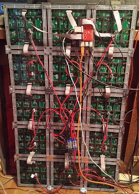
I am building my biggest LED wall yet. It should be 8 feet by 4 feet when done.  It consists of two panels each 4 feet by 4 feet in size.  Each panel is made of 32 P5 64x32 Led matrixes. This first picture is me putting together one of the panels

Currently I only have enough of the matrixes to build two 4 by 6 panels.  Here the data and power cables are added.


This picture shows the controller is added to the panel. Power supplies are external so that the panels fit flat to the wall.


This is a demo picture testing the first LED panel.


I have built the second panel but it has two bad LED's to resolder, should have it running soon. Here is a picture from before they were mounted on the wall.


Tuesday, October 14, 2025

Doubling the size of a LED sign

 I have two 40" by 16" LED signs. Each one has five by two of the 32 by 32 P6 LED arrays. I thought they were identical signs and thought that I could combine them to make a sign twice as big.  The first issue is the height, I am limited to 2 feet of height.  So the options are 7 by 3 or 6 by 3 LED arrays.  For 7 wide I need one more LED panel so I tested it with a spare panel that apperared to match.  Well, two of the existing panels had a bad LED and the odd panels blue color was a real mismatch.  So 6 by 3 is the best arraingement.

The next problem was that one sign had 35x35 LED's and the other had 27x27 LED's.  However in a test setup they completely match in colors and intensity except in the lowest brightness settings. So that problem can be ignored.

The next problem is extending the exrtrusions to make them wider, instead of 40" wide I needed 48" wide.  I designed and printed a 3D part that fits inside of the extrusions to allow two extrusions to be joined together.

The next problem is that one sign used magnetic devices to hold the panels to the braces but the other sign used double sided foam for that purpose.  I decided to use some of the magnetic holders and to design and print my own spacers for the rest of the sign. This holder can be used to space the panels back to match the extrusion but if you are using a 3" by 1" aluminum frame it can be reversed to space the panels back from the front edge.


This picture shows the center strip where magnets fasten the panels to the Metal.  However the magnets do not work and plastic wire ties were needed to hold the panels in place.

This picture shows the power supply mounting arrangement. There are three power supplies of 40 amps each.

This picture shows the spacers that fasten the panels to the extrusions.  Also you can see where two extrusions were fastened together in this picture.

Friday, October 10, 2025

Make your own LED sign

I have made my own LED sign from scratch and have also made one by adding parts of two signs together to make a bigger one.

 I wanted to use 3" by 1" Aluminum for my LED sign but that cost too much. I had some 2.75" by 3/4" Plastic U channel and I used that instead. The corners were 3D printed using PTEG for dtrength. This could be easily enlarged to work with 3" aluminum as well.

The LD panels were spaced back using 1/2 inch spacers so they are flush with the front of the sign.  I used lots of silicone caulk around the edges of the LED panels.

This first picture shows the back side of the completed LED sign. It used two 5 volt 60 amp power supplies.


This is a close up of the 3D printed corners.  The back cover slides into these corners but it first needs a diagonal cut to match the shape of the corners.

Monday, September 8, 2025

Build Your Own LED Wall

I have been building my own LED walls.  So far I have two of them, one uses P4 indoor Panels the other uses P5 indoor panels.  


All of the panels were purchased at huge discounts.  Here are some pictures of my eBay purchases for a total of 35 P4 panels.  You have been told that you cannot intermix LED panels.  I have used three different types of panels and a totally red, green or blue image shows that they are obviously not matched.  However, real images dont show up the mismatch nearly as much!


Most P6 panels can be connected together by metal brackets that have holes on 1 inch centers and are found at most hardware stores. P4 and P5 panels use 3D printed junctions and 3/4 by 3/4 aluminum rails for the outside edges.  I also have a mounting adapter for 5A-75B receiver cards that can control up to 8 strings of LED panels on thingiverse.
This is a schematic of a typical setup.  The 5A-75B can only control strings of 6 panels with the default lessings.


Here are two pictures of some assembled LED walls.  The second does not have the top and bottom aluminum rails installed and the vertical rails were moved to the middle of the panels so they would match the hanging loops spacing.


To keep the LED walls so that they are almost flat to the wall I use external power supplies.  Each power supply can run 15-20 LED panels.  I use 12 Gague speaker wires and 50 amp connectors to connect the power supplies to the panels.  I have soldered the power cables together or used binding posts to connect the power cables together.  The white plastic binding posts with holes that you insert the wires into seem to work the best.

Here is a picture of a P6 panel system with binding posts connecting the power lines together.  You can see that is is more dangerous than soldering the wires, and though matter how tight the screws are, somehow the wires will come loose.

The next pictures show the two types of binding posts, Regular and white with holes for the wires.


There are three different type of LED panels but did you notice that in the pictures above?  Here is red, green, blue and white test pictures. The blue makes the location of the three type obvious.  the red and green are harder to tell them apart.


Now the white picture has a different shade on the left side.  Why?  It was power supply overload!  The left side is using a different power supply.

Wednesday, May 21, 2025

How to repair LED matrix panels.

A few years ago I had two P3 LED panels with missing LED's in the corners due to being beaten up in shipping.  Recently it happened again, this time three P5 LED panels had missing LED's from shipping abuse.  In another case I bought 18 P6 panels that were likely bad before they were shipped.  Every panel had bad LED's, some had as many as 30 LED's that were not working out of the 1024 on the panels. At first I repaired them to where 1-5 LED's were still out, but then with a better soldering iron tip I was able to get them to 100% working.

I want to show you how to repair minor problems with LED matrix panels.  Usually it is a corner LED that is loose or missing.  You can buy reels of 100 LED's for about $6.  In the P3 and P5 panels they were 2121 LED's.  The P6 panels had 3535 LED's.

First remove the almost invisible screws near the missing LED.  Then lift the panel screen and make two small cuts in the screen as can be seen in the next picture.  Remove the cut out piece. Set the screen back down.  Clean up the solder pads, leave some solder on them.


Then slide in the new LED into place with the panel powered up so you can see if it is oriented correctly by it lighting up.  Then, while holding the LED down with a small screwdriver, solder the two visible pins into place.  Next, lift the screen and prop it up.  Solder the two pins that you cannot see by "feel".  Then test the screen to make sure that it is working now.


Wednesday, May 7, 2025

Signs, Signs, Everywhere Signs!

I have just finished my latest book "LED Sign Projects".  I am not happy with the cover.  Besides being off center its kind of redundant.  LOL.  Also they used to add a page saying it is a proof.  But if you were happy with it you could remove that page and sell it.  Now they have "Not for Resale" on the cover!  The proof costs about the same as buying one so why do that to it!?!?


Another cover picture was "Signs, SIgns Everywhere Signs" after the song from the 70's.  But it lacked contrast.  Most cameras do not take accurate pictures of LED signs.  Would this make a better cover image??


I just completed one of my biggest signs ever.  Its 5 feet wide and 3 feet tall, the equivalent of a 70" TV screen.  There are 30 of the 32 by 64 P5 LED panels for over 30,000 pixels.  The resulting image is awesome!  Unfortunatly the pictures did not turn out well.  

This picture was taken before I put the top and bottom aluminum rails on it.  I use Steel L brackets at the corners to reinforce them and the mounting eyelet goes into that steel L Bracket as well.  So most of the weight is carried by the vertical aluminum rails.  I use external power supplies that way it is almost flush to the wall when it is hung up.


Here are some of my other LED signs from the back side.  This is similar to the one shown above.  Note that the panel joiners are all 3D printed.  I tried 3D printing the edges but they broke too easily so I use 3/4 inch L aluminum extrusions found at most hardware stores.

This is a water resistant version featureing 4x5 or the 32x32 pixel P6 LED panels.


Monday, May 5, 2025

Using LED strips to light up a Street sign instead of fluorescent bulbs

A couple of years ago I replaced the non-working five foot fluorescent bulbs in our church street sign with LED's.  However the horizontal strips were visable and became annoying.  So I came up with the idea of using edge lighting.  The LED strips would be on a metal surface so they would be less likely to overheat and burn out.  

I had some 130 per Meter or 36 per foot 2835 SMD LED strips.  They were 10 Meters or 394 inches or 32.8 Feet in length.  They are soft white and run off 12 Volts.  The total power is 90 watts per 10 meters length.  I used two of these strips for four laps around the inside of the sign.  I think if I was to buy them I would get bright white LED's instead.


This is the results as seen at night.  No more horizontal strips of lights!  It does dim a little in the center but it sure looks better.  Now to get a bigger LED sign!


Saturday, March 8, 2025

ESP32 HUB75 DMA Hue Value Spectrum demo

The Hue Value Spectrum demo is beautiful, cameras do not do it justice.
This is found at https://github.com/mrcodetastic/ESP32-HUB75-MatrixPanel-DMA


This software connects to just the input port of the LED array.


The issue with this software is that it it too fast.  The speed results in noise from the 3 volt logic driving the 5 volt panel.  You have to play with the ground wires and keep the ribbon cable as short as possible to prevent noise and even then there are faint blinking LED's from th noise issue.

Another issue is the software does not support "Strange" LED panels like most 8S outdoor panels.


Aurora Demo on ESP32 with a 16S 32x32 LED panel

This is the Aurora Demo working on 32x32 RGB LED matrix panel with an ESP32 Processor.  I bought a circuit bard to do this but could not get it to work, so I went with jumper wires and it worked almost perfectly from the start!

This wiring arrangement uses two sets of jumper wires going to both the input and output of the LED panel.  This makes it almost impossible to transfer it to another panel to test different ones to see if they are supported inthe software.


The wiring looks like this:


This wiring makes it difficult to add more panels or to try using another panel.

Thursday, February 13, 2025

New Big LED sign powered by Raspberry Pi

I have made another big LED sign, but this time it is powered by a Raspberry Pi.  At first I used the Adafruit Hat ,but I have upgraded to the three HUB75 Hat from ElectroDragon! This enalbes three chains of LED arrays. So far I have 5 32x32 panels in each chain but I will likely expand that.

This is a view of the back of the assembled panel. I am using metal brackets to hold the panels together as they have on inch spacing. 24mm is ideal as the one inch spacing leaves about a two mm space between the panels. I have a 3D printed version of the brackets on thingiverse and have used them in other designs.

Here is a couple of pictures of the panel being lit up. The text demo is limited to one line of panels.

There are several demo programs to check out the proper operation of the Raspbery Pi adapter.


Here is a link to the video of the demos;

https://youtu.be/44ykJb_ZB7A?si=ylKY5zBix4FU4i2X

Sunday, February 9, 2025

Testing LED panels for bad LED's

I have written two programs to test LED panels after someone sold me a pile of them with many bad LED's.  Some panels had over 30 LED's that were not working.  He also shipped them with no padding between the LED's!  This resulted in smashed LED's and some of the alignment nubs were broken off.  Fortunatly with some soldering I was able to reduce the number of bad LED's to 3 or 4 per panel.  Now I can use them for testing out programs and configurations.  Some LED's had broken runs but most of them just needed to be resoldered.

The first program tests the colors and leaves the panel white for quickly testing if the LED's just soldered are working.  This does not work on 16S panels for some reason.

// RGBcolors test for Adafruit RGBmatrixPanel library.

// For testeing LED arrays for bad bits.

#include <RGBmatrixPanel.h>

#define CLK  8   // USE THIS ON ARDUINO UNO, ADAFRUIT METRO M0, etc.

#define OE   9

#define LAT 10

#define A   A0

#define B   A1

#define C   A2

#define D   A3

// Does not work with 16S panels if you add "D" nothing happens!

RGBmatrixPanel matrix(A, B, C, CLK, LAT, OE, false);

void setup() {

  matrix.begin();

   // fill the screen with colors

  matrix.fillRect(0, 0, 32, 32, matrix.Color333(0, 7, 0));

  delay(1000);

  matrix.fillRect(0, 0, 32, 32, matrix.Color333(7, 0, 0));

  delay(1000);

  matrix.fillRect(0, 0, 32, 32, matrix.Color333(0, 0, 7));

  delay(1000);

  matrix.fillRect(0, 0, 32, 32, matrix.Color333(7, 7, 7));

  delay(1000);

}

void loop() {

}


The next program is for sorting LED panels by how they are internally wired.  There are 16S, 8S (There are many varieties of 8S) and 4S panels.  It scans all LED's one at a time.


I could not get this to work with the normal drivers so I wrote my own using "bit banging".  Its slow but works great!  Note:This program was improved in March of 2021, it runs much better now!

// RGB bitbang test bits by scanning

#define CLK  8  

#define OE   9

#define LAT 10

#define A   A0

#define B   A1

#define C   A2

#define D   A3

#define R1  2

#define G1  3

#define BL1  4

#define R2  5

#define G2  6

#define B2  7

int tbit;

int row;

int col;

void setup() {

  pinMode(A, OUTPUT);

  pinMode(B, OUTPUT);

  pinMode(C, OUTPUT);

  pinMode(D, OUTPUT);

  pinMode(CLK, OUTPUT);

  pinMode(OE, OUTPUT);

  pinMode(LAT, OUTPUT);

  pinMode(R1, OUTPUT);

  pinMode(G1, OUTPUT);

  pinMode(BL1, OUTPUT);

  pinMode(R2, OUTPUT);

  pinMode(G2, OUTPUT);

  pinMode(B2, OUTPUT);

  }

void loop() {

  // Set sequential bits

  for (row=0; row<16; row++){

    for (col=0; col<64; col++){

      for (tbit=0; tbit<64; tbit++){

        digitalWrite(R1, LOW);  

        digitalWrite(G1, LOW);  

        digitalWrite(BL1, LOW);  

        if (tbit <= col){

          digitalWrite(R1, HIGH); 

//          digitalWrite(G1, HIGH); 

//          digitalWrite(BL1, HIGH); 

        }

      digitalWrite(CLK, HIGH);  

      digitalWrite(CLK, LOW);  //Clock data in

      } 

    // latch and display results

    digitalWrite(OE, HIGH);  // disable output while latching data.

    digitalWrite(LAT, HIGH);  

    // select next column if it has changed

    digitalWrite(A, LOW);

    digitalWrite(B, LOW);

    digitalWrite(C, LOW);

    digitalWrite(D, LOW);

    // update row selection

    if ((row & 0x0001)>0)digitalWrite(A, HIGH);  

    if ((row & 0x0002)>0)digitalWrite(B, HIGH);  

    if ((row & 0x0004)>0)digitalWrite(C, HIGH);  

    if ((row & 0x0008)>0)digitalWrite(D, HIGH);  

 //   delay(5); // dim display

    digitalWrite(LAT, LOW);  

    digitalWrite(OE, LOW);  

    delay(50);

    }

  }

}

Sunday, February 2, 2025

Explaining the different types of LED Arrays

Not all LED arrays are the same, there are many varieties within a set size and set amount of LED's.  There are the P numbers.  P10 means 10mm LED spacing.  P6 is 6mm spacing.  P3 is 3mm spacing.

Then there are the S or scan or row select numbers.  Typical S numbers are S4, S8, and S16.  But they even vary within these numbers!  Lets start with a 16S arrangement.  In a 32 by 32 LED array there are two 32 bit shift registers one for the top half and one for the bottom (As well as one for each color).  Then there are 16 row selectors that select what two rows are currently lit up.


Next there is an 8S LED array.  Withing a 32x32 array there are four 32 bit shift registers.  The top two and the bottom two are sequential. (This is for each of the three colors) Then there are 8 row selectons.  These select what four rows are currently lit up.


Now things get tricky.  Some arrays do not follow the normal pattern.  For instance the modified 8S panel depicted below.  These are not compatable with some controllers.  There are two 16 bit shift registers and a 32 bit shift register for the top half and the same for the bottom.  (This is for each of the three colors)  The shift register sequence is the top 16, then the middle 32, then the other top 16 bits.


So not only are you dealing with color differences between different batches you are dealing with scanning differences.  You cannot mix an 8S and a modified 8S in the same chain of LED arrays.


Tuesday, January 28, 2025

Big LED sign with 6x4 of 32x32 P6 LED panels

My latest LED sign is by far my biggest LED sign yet!  I purchased a pile of P6 32x32 LED panels on eBay for about $10 each.  The seller even included the cables needed to get it to work!

Here is a picture of it with a TF-QS3N Controller.  It uses PowerLED to set it up from a computer over a newwork.


This is the back side of the sign as I was assembling it.  The sign is now over twice the size shown in this picture.

Here is a newer picture at 4 by 7 panels.  It is now 5 by 7 panels in size and growing!  I hope to get to 5 by 8 panels but the model numbers of the next panels do not match and the color balance might be too far off to intermix them.


One option to connect the panels together is these metal brackets available at most hardware stores at four for $5.00.  Thes have a hole spacing of one inch (24.5mm) and the panel mounting holes are 24 mm so there is a 1.5 mm gap between the panels if you uses these brackets. 

I have 3D printed my own brackets for connecting the panels.  They were designed on TinkerCad.  The STL files are available on thingiverse. 

Here is a video of when I first got them working.