Showing posts with label 3D printer. Show all posts

Wednesday, December 31, 2025

I bought a new 3D printer again this year a Creality Ender 3 V3 SE

I bought a new 3D printer again this year. It is a "refurbished" Creality Ender 3 V3 SE.  Last year I bought  Ender V2 and upgraded it with a quiet motherboard.  I had purchased a CR Touch Auto Leveling kit for it but did not install it. Now I know how important the auto leveler is!  I had also gone through three build plates on the old printer and then bought a TRONYX glass build plate. The TRONYX glass build plate is about 1/2 inch too small but worked GREAT!

This is a close up of the new printer, it looks more refined or finished than the old one.


This picture compares the old printer to the new printer.


Friday, November 13, 2020

I am Rebuilding my 3D Printer with several new improvements

I am Rebuilding my old 3D Printer with several new improvements.  The parts needed have gone way down in price.  In fact you can get a 3d Printer kit on eBay for a little over $125.  That would sure save a lot of headaches when it comes to mismatched parts.

Here is the old 3d Printer, it was mostly home made other than the print head.

Here is the new one still under construction, it has several purchased parts that are a fraction of what they cost just a few years ago.

The new frame was purchased on eBay.  Someone is dumping them to the lowest bidder starting at only 5.99!  Sometimes there is no bid even at that price!  The new frame has the motor mounts built in making that part easier to do and more accurate.  The frame also comes with a mounting place for the LCD display too.  The frame did not come with front and back pieces so I made them myself.

The new print head was purchased for under $25!

The 10MM bearings under the Y axis were purchased with the mounting brackets.  I had 3D printed the mounting brackets on the old one but they kept breaking and were eventually glued together.

The Z axis is now using 8mm leadscrews with matching nuts.

The power supply is mounted in the frame on the right side.

Now to get it wired up and working!


Monday, January 16, 2017

DIY 3D Printer Updated to a PRUSA I3 Compatible Version

I am working upgrading  my 3D printer to a PRUSA I3 Compatible Version.  I will also be updating my book "Inexpensive 3D Printer Projects" once the upgrade is completed and working.  Hopefully there will also be a all metal version of the PRUSA i3 3D printer in that book as well.

One of the issues so far is that the PRUSA i3 uses a 5 mm threaded rods for its lead-screws.  I wish that there was a 8 mm compatible version available.  I have found a alternate X axis end design that I can print out that does support 8 mm lead-screws.  Here is a link to the upgrade: http://www.thingiverse.com/thing:1140733. The other option is to purchase the all metal X axis for the Geeetech i3 printer.  I am also making a normal PRUSA i3 printer to verify that all of the parts are interchangeable with my design.

This is what the rebuilt 3D printer looks like so far:

Here is a progress report picture on rebuilding the 3D printer.

It now has the Y platform installed and the Arduino is in place as well.

This picture shows the wiring (mess).


Here is the results of the first test run.  The X axis belt skipped and caused it to print in the air after a few passes.

There were some more failures before I changed the extruder and fixed a wiring problem.

After a couple of calibrations it is now working.


This is what the finished elephant looks like.  My Z axis was off (3333 vs 4000) so it is shorter that it should have been.

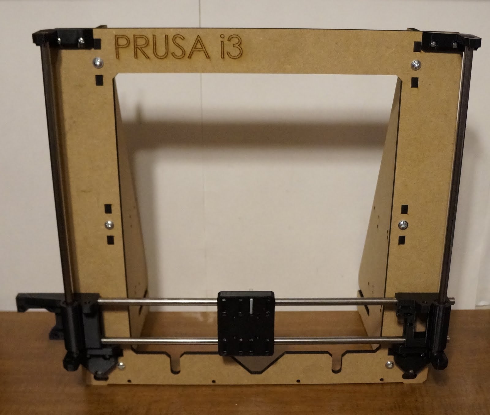
To verify compatibility I am also building a PRUSA i3.  Here is the frame with the printed parts.

Then I switched to my home made metal parts.  I need to cut the Z axis shafts off so they are shorter.

I spray painted the frame with about 4 coats of gloss black paint.  It looks a lot better now.

I have added a Geeetech i3 all metal X axis to the Prusa i3 frame!  The secret is the home made motor mounts.
This is what the completed GeeeTech i3 all metal 3D printer on a PRUSA frame looks like.
This is the electronics for that 3D printer.

Tuesday, December 23, 2014

DIY 3D Printer - Printing Small Parts

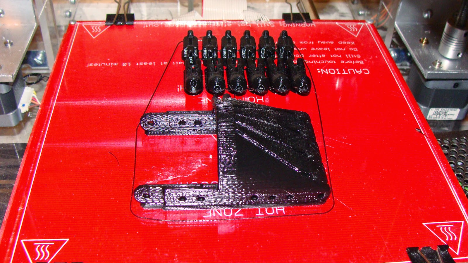
Here is a picture of a printed 3D hand.  When I first tried to print it I had fingers flying all over the place.  I even tried gluing them down to no avail!

Here is what you can do to make printing small parts possible.
1. Clean the glass with a razor blade.
2. Treat the glass with acetone and/or hair spray.
3. Print a 3mm "Brim" around the base of objects.
4. Print the center or "infill" first, then the edges.
5. Use a soldering iron if needed to remove "bumps".
6. Slow down the acceleration to 1000 or 2000.

Here is a video of the results.
http://youtu.be/6_5nY8F2hQg?list=UU49j5FVUO2KIFyH2IXmGXjg

The problem is that the plastic expands in the Z axis as it cools.  Then when the print head goes over it the part is impacted and sent flying.  If the "infill" is printed first then the edge does not need to be passed over to print the infill.

Monday, November 24, 2014

MY DIY 3D Printer update

Here are a couple of tricks I have learned.  When I first started printing everything worked fine.  Then after making about 5 things they started coming loose.  To clean the glass use nail polish remover (Acetone) on a Kleenex.  Then apply 2 or 3 squirts of hairspray.  You may need to spread it around a little.  That surface preparation results in the best adherence of the printed parts.

I have made several upgrades to my 3D printer.  Like for instance an oversize fiberglass Y axis carriage.


Here it is printing out a Mendel90 X axis motor end.  I am working on printing out all the parts of the Mendel90 3D printer.


I used some packaging strap to hold the ribbon cable up.

This is a picture of my new extruder's hot end.  I need to mount the fan to something but it has survived hanging from the wires for quite a while.  Here is a link to a video showing it in operation. http://youtu.be/MVh2b1nGNW8?list=UU49j5FVUO2KIFyH2IXmGXjg

Here is my growing collection of "Bricks".  Things that did not turn out like they were supposed to.  I have made far too many bricks, so now I built the new extruder and hot end.

Here is a link to my latest video.
http://youtu.be/nLawLOgIe3Y?list=UU49j5FVUO2KIFyH2IXmGXjg

Wednesday, October 15, 2014

Building my own 3D printer part 3 and the first video


My 3D printer had its first test run last night.  So far I need to replace the X axis stepper motor it has a bad connection inside of it somewhere as can be seen in this video on Youtube.

http://youtu.be/s77h1BQ-EVQ

Here is a picture of the jumpers to convert the Ramps board to a printer 25 pin interface.  I only connected to the pins that I needed for X, Y, and Z for Step, Direction and Enable, they are blue, green and yellow.  The enables are all connected to ground.  Then I also needed to connect to ground and 5 Volts, they are yellow and red, the top two connections..


Here is another video of the DIY 3D printer this time it is running with and Arduino Mega.

http://youtu.be/YemKKhmJT2o

Here is a picture of the Ramps wiring.  The heat bed is not wired up yet.
Here is the wiring with the heat bed wires in.  I spliced the ribbon cable into some 14 gauge stranded cable and covered the splice with heat shrink.

Here is the third video.  This was my first extrusion attempt.


Here is what I got from my first attempt at making something.  It was supposed to be a 8mm bearing support.


Tuesday, October 7, 2014

Building my own Mendel 90 3D printer part 2

My 3D printer is coming along quite nicely but slowly.  I have started doing the electrical wiring as can be seen in this picture.  Notice the custom made aluminum motor mounts and the use of standard "off-the-shelf" parts throughout.  My next book will give the details of construction it will be titled "Inexpensive 3D Printer Projects".


I purchased standard ends for the X-Axis ends but I have come up with plans as to how to make my own X Axis ends.  I really think even the X Axis ends can be made with standard parts and a piece of Plexiglas or aluminum to hold it together.  The only tricky part would be the "Nut bracket".  That could be made out of Plexiglas.  Just drill a 1/2 inch hole in it and then melt the 5/16" nut into the hole.

Here is a picture of my homemade X axis carriage.  I had to cut the 1/2 inch pipe supports to fit them in the space available (There is approx 2.05 inches between the rails).  The two holes at the back are for mounting the Extruder. The holes at the front already existed but they are for the belt clamps.  The center hole was just a little over 1.25 inches in diameter but it was not big enough to lower the hot end down through.  I had to disassemble it and reassemble it through the hole.  I need to cut off 1/2 inch at the front as it is not needed.  I changed the design and moved the holes out 1/8 an inch.  Then I countersunk them and used flat head 6-32 screws.  Now the print head sits flush.

It is almost done!  Just the 25 pin connector at the bottom right and the heatbed to wire up and it will be done.  Here is what it looks like at this point.


Tuesday, September 23, 2014

Building my own 3D printer based upon Prusa and Mendel90 designs

I have been trying to build my own 3D printer.  I am trying to use "off the shelf" parts as much as possible. I did end up buying X axis ends on eBay.  I designed and made my own stepper motor mounts.

Here is a picture of the frame as I first assembled it.  The blue tape is so I can write on it for my hole markings.

Right now I am stuck on the lead screws for the Z axis.  The holes for the nuts are .55 inches across and they are supposed to be for 8mm nuts.  But 8mm nuts are .51 inches and 5/16 nuts are .5 inches. Both nuts rotate freely in the hole as the hole is for a nut that is .55 inches across.  The nuts that are found on hollow electrical threaded pipe commonly used in table lamps fit perfectly.  One of these is seen on the right side below.  However that would be hard to adapt that to the 5mm stepper motor shafts!


Some of the other problems I have faced so far include:

The stepper motors came with gears on them.  I used a gear puller to remove the gears.  When I connected the motors up to the lead screws I discovered that their shafts were bent so much that the top of the lead screws rotated in about a one inch circle.  I had to get new stepper motors.  When I installed the new stepper motors I discovered that the problem was actually the 5mm to 8mm shaft coupler!  It was drilled so crooked that it causes the lead screw to rotate.

As I said above the holes for the nuts in the X axis ends are .55 inches across and both 8mm and 5/16 nuts spin freely in them.  I might have to make my own "nuts" out of aluminum using a 5/16 tap.   Wow was I really off on that one.  It turns out that the nut holes on the top are .55 inches but the nut holes on the bottom are .51 inches!  So I was just looking at the wrong nut holes.

When I assembled the Y axis carriage and slid it towards the back it returns back to the front on its own!  That is because the rod spacing varies by 1/8 of an inch causing the bearings to bind.  I enlarged the holes on the back side and adjusted it so the platform moves smoothly now.

The 8mm bearings are terrible.  They do not move smoothly and they loose some of their balls every time I remove them from the rods.  I might have to replace them with better ones from another vendor?

Some of the 8mm rods are from printers and scanners.  The one on the right side is a tiny bit bigger than 8mm.  I used emery cloth to take it down a little bit so that the bearings move smoothly.

I used 10mm rods (from scanners) and bearing for the Y axis.  They work so much better than the 8 mm bearings.  However their outside diameter does not fit either 1/2 or 3/4 pipe holders.

The spacing of the z axis guide rods varies by 1/8 of an inch from the top to bottom.  That is a tricky measurement since there are rod holders at the top and a home made motor mount at the bottom.  I will have to move the rod holders in about 1/16 of an inch on each side to fix the problem.

While testing the Y axis I realized that the gantry is at the wrong position.  When I move the Y carriage back the print head will not reach the front edge.  I had to unbolt the gantry and move it forward one inch to resolve the problem.  It was six inches from the back edge but it is now 7 inches from the back edge.

The Y axis bearing holders hits the stepper motor that is mounted under it.  That is because I mounted the stepper motor all the way to the right.  It needs to be moved at least an inch to the left. It also needs to be moved so that the wires to the Y platform can be run in the center, the drive belt is there currently.

I cannot put nuts on the Y axis hot plate screws.  The bearing holders are too close to the front and back edge of the Y platform so there is not enough room to put the nuts on the hot plate screws.  I will have to move the Y axis bearing holders 1/4 inch further from the front and back edges.

I tried to mount the Arduino Mega, but like all Arduino's the mounting holes are an afterthought.  I wanted to have screws come through the plastic, then a nut, an insulator then through the Arduino then a last nut.  However the nuts cannot be on that side.  I am trying to rework it to use the standoff's that are used for ports on a PC.