Wednesday, May 23, 2018

Rebuilding LAB Series LS800 Amplifier with a L-15 Amplifier

I am rebuilding another power amplifier.  This time I chose the L-15 amplifier because it fits in the heatsink.

The L 15 amplifier compared to the old circuit board for size.
 The amplifier totally dissembled into pieces.
 The back panel of the amplifier.
Here is the ebay ad for the replacement amplifier.
The L15 fits nicely in the heat sink
I am using 4 pin power connectors for 5.25 floppy drives for power and ground.  Red is positive, yellow is negative and black is ground.
Here is a picture of the old front panel.  I will replace it with two LM3915's.
This is the first test.  Power is at + and - 62 VDC.  Lots of gain, I had to turn the volume way down.  Still to go are the input jacks and volume controls.

I have been comparing some of the amplifiers that I have worked with:

L-10 Amplifier:
Size 200x41.5x?? mm
8 Ohm 100 Watts
4 Ohm 200 Watts
2 Ohm 350 Watts +-55VDC
Transistors 3 EA: A1943 C5200

L-15 Amplifier:
Size 150x40x?? mm
Size 5.9x1.57x??"
8 Ohm 150 Watts
4 Ohm 300 Watts
2 Ohm 600 Watts +-55VDC
Gain 36x
Transistors 3 EA: IRFP240/IRFP9240

L-20/28 Amplifier:
Size 110x65mm (L-20)
8 Ohm 200 Watts +-65V
4 Ohm 350 Watts +-60V
Gain 34x
Transistors 4 ea D1047 B817
Note: L-28 includes capacitors and speaker protection

PR-800 Amplifier:
Size 245x65x30mm (or 195x90 with 4 Capacitors)
Size 9.64x2.55x1.18"
8 Ohm 500 Watts +- 95VDC
4 Ohm 1000 Watts +-90VDC
2 Ohm 1000 Watts +-65VDC
Gain 40x
Transistors 4 ea TTA1943 TTC5200
Note: Includes Capacitors and Speaker protection
Note there are 2 sizes one with 2 capacitors and one with 4 capacitors.

NJW0281/NJW0302 450W+450W HIF
Size 259x73mm
8 Ohm
4 Ohm 450 Watts +-85VDC
Gain Very Low - needs preamplifier
Transistors 4 ea NJW0281/NJW0302

I think I can fit the PR-800 amplifier version with two filter capacitors so I will try to upgrade to that amplifier instead.  It is coming from China so it will take a while.  Please stay tuned. The PR-800 version is in another blog post.

I am rebuilding the VU meters.  I did purchase some LM3915 kits but they only have 10 LED's and I have 12 holes to fill.  I also used round LED's instead of the flat ones that came with the kit. But that version only has 10 LED's.  So I stripped a board from the amplifier bare and installed a LM3915 instead leaving room for more circuitry.
However the rebuilt VU meter was barely visible!  So I had to replace all of the LED's with newer brighter models.  Now to add the two top LED's.  I am planning on using a dual op amp for that job.


Saturday, May 5, 2018

Ford Taurus Passenger Blend Door Actuator

My wife's car had the heat stuck on for the passenger side only.  It was way too hot and it would not turn down.  The problem was a motorized door that was stuck.

Here is an excellent video on how to change the actuator.

I used my fingers to disconnect the electrical connector and that might be easier to do before the actuator is removed.  It is identical to the other connector to the right so you can see what your are feeling for.  Basically you push in a small tab in the center and pull up on the wires.

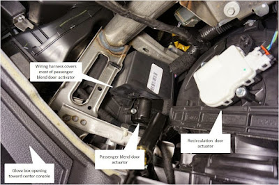
Here is an great picture of what to look for behind the glove box.

Source: http://www.taurusclub.com/forum/114-5th-6th-gen-maintenance-repair/244434-driver-side-blows-cold-passenger-side-blows-hot.html

This is how to test the heating and cooling system.
Turn the heating/cooling system off before you start.

The self-test can be initiated after cycling the ignition switch from OFF to ON.
For the self-test, press the OFF and DEFROST buttons together and release them.
Then press the AUTO button - ALL within 2 seconds.
The display will show a moving bar-graph icon for 20 seconds.
If diagnostic codes are present, they will be displayed.
My codes were "12 42" and "22 67"
When done press any button to exit.
Wait 30 seconds to turn the key off for the computer to re-calibrate.

Here is a picture looking into the glove box area.

This picture is going in a little closer.  I moved the white wire harness down out of the way.

Here is the tool setup I used to get to the back screw.  I had to purchase a 1/4 inch universal joint for $5 that you cannot see in the picture.

Here is what is inside of the actuator.  You can test the motor with a 9 volt battery.  The two connections to the motor are on the right side (back) of the motor.  My motor turned a couple of times and stopped.  I thought maybe the mechanics were stopping it, but no it was the motor itself.
***UPDATE ***  A year later I had the same problem again!!  This time I cut away the wiring cover above the actuator with a razor knife.  Then I used wire cutters to cut the plastic next to the wire so as to not cut the wires.  Then I drilled a tiny hole and put a 2 inch deck screw into the black part of the actuator so that it can be locked in place on either hot or cold depending on the time of year.