Wednesday, November 18, 2020

Installing and Upgrading Solar Panels to 50 Watt panels sold on eBay

 A few years back I bought some solar panels at a Hamfest.  I was disappointed to find out that they are only 10 watts each. By todays standards that is very little power per square foot.  I also bought a solar battery charged on eBay to connect the solar panels up to a battery.

Here is what my very basic setup looks like.  I do not have any "Load" connected yet but I do have an inverter to convert 12 volts to 120 VAC.  The charger has two USB jacks to charge your cell phone.


This year I decided to update the solar panels to some higher power versions.  I bought two 50 Watt panels on eBay for under $60.  This picture is of the ad that appeared on eBay.

This is a bottom view of one of the new panels.  Note the box with a cord coming out of it.

This is a top view of one of the new panels.  The new panels are 1/2 the size of the old panels.

This is the accessories bag that came with the panels. There is a device to plug into a cigarette lighter to charge a car battery and clips to clip directly onto a battery.  Then there are four suction cups that I suppose is how you are supposed to mount the panels.


So there is no easy way to mount these panels like the old panels were mounted, and there is no easy way to hook up these panels to the battery charger controller.  They do have a "Barrel" type of power connector like what is found on many AC Adapters.

This next picture shows what happens when you try to mount the new panels to the old 3 foot by 1 foot solar panels.  The box on the back of the new panels creates a big curve that tends to pop the suction cups off.  This is not going to work!

This picture shows how two of the new 50 watt panels can fit on one of the old 10 watt panels.  That should take me from 10 Watts to 100 Watts per three square feet.  However, I would not recommend this type of mounting as the suction cups repeatedly failed when trying to take this picture.

I am thinking I will need to make a frame out of wood or metal and then mount the new panels on the frame.  Then the frame could be mounted to the roof.

I installed the new panels and after the first snow storm they stopped working!  I have yet to find out the problem as they are under the snow.  I mounted them on an angle so the snow would slide off them but it stays on top of them.  The old panels worked even when under the snow.


Sunday, November 15, 2020

Sony BDP-S1500 Blue Ray DVD Repair

 I purchased a Sony BPD-S1500 Blue Ray DVD player because I had accidently bought a Blue-Ray DVD.  After about a year of occasional use, it stopped working.  The symptoms were that the logo would show up, then the screen would flash blue, then nothing.  The DVD tray would still open and close but there was nothing on the screen.  It looked exactly like a Raspberry Pi trying to run on a lame power supply.  I opened up the case and discovered four pads next to the power jack.  These would normally be used for power filter capacitors to help stabilize the power.  The front two pads are power and the back two are ground.  I added a 100uF 25 volt capacitor to the pads.

The unused pads are circled in red in this picture.


Here is the capacitor I added, the leads should have been cut shorter.

Sure enough this simple repair fixed the DVD player.  I am watching a movie while I write this!


Friday, November 13, 2020

I am Rebuilding my 3D Printer with several new improvements

I am Rebuilding my old 3D Printer with several new improvements.  The parts needed have gone way down in price.  In fact you can get a 3d Printer kit on eBay for a little over $125.  That would sure save a lot of headaches when it comes to mismatched parts.

Here is the old 3d Printer, it was mostly home made other than the print head.

Here is the new one still under construction, it has several purchased parts that are a fraction of what they cost just a few years ago.

The new frame was purchased on eBay.  Someone is dumping them to the lowest bidder starting at only 5.99!  Sometimes there is no bid even at that price!  The new frame has the motor mounts built in making that part easier to do and more accurate.  The frame also comes with a mounting place for the LCD display too.  The frame did not come with front and back pieces so I made them myself.

The new print head was purchased for under $25!

The 10MM bearings under the Y axis were purchased with the mounting brackets.  I had 3D printed the mounting brackets on the old one but they kept breaking and were eventually glued together.

The Z axis is now using 8mm leadscrews with matching nuts.

The power supply is mounted in the frame on the right side.

Now to get it wired up and working!


Thursday, October 8, 2020

Chevy HHR Windshield Wiper Bushing Replacement

Recently one of the windshield wipers on my HHR stopped moving.  I removed the plastic cover and discovered that the wiper arm had become disconnected.  One of the little plastic bushings would no longer hold onto the ball joint it was supposed to be connected to.  After chiseling off the catches I removed the plastic bushing and figured that it would be no problem to replace it. NOT!

First I tried Dorman kit 49455, they were way too big.

Next I tried Dorman kit 49449, they were way too big.

Next I tried Dorman kit 49447, it is a 10 bushing assortment kit, two of them actually fit the ball joint.  The ones that fit were the ones that are shaped like a cowboy hat.  To get them to fit on the arm, I had to trim the bottom ridge off to make it smaller.  Then a pair of channel locking pliers squeezed the bushing onto the ball joint.

This is what the finished repair looks like.


I used channel locks to squeeze the bushing into place.

This is what the assembly looks like under the plastic cover.


Monday, September 28, 2020

Ode to Projectors.

Many years ago, while visiting a church, I made the mistake of closing my hymnal, because I knew the words to the song by heart.  Far be it from me to show such disrespect to the writings that are second in line behind the Bible.  The preacher rightfully called me out and warned me that crazy Pentecostals (I was a Methodist) like me will end up in an insane asylum within 6 months.

So when I moved to Virginia Beach I did the right thing and went to a Pentecostal church. There the hymnals had been replaced with a slide projector, so I would not offend anyone by not using the hymnal.  The slide projector held 80 slides, at two slides per song, that’s 40 songs per carousel.  There were three carousels but we tried to keep the songs we used the most in one carousel.  Being a techie guy, I was quickly put in charge of running the projector.  There was an notebook with an index that kept track of what song was at what position but after a while you memorized the song numbers. Sometimes, almost magically, one of the slides would be upside down or turned sideways.  That had to be quickly corrected!

A slide projector

To add a song, you had to type the song perfectly on a typewriter.  Then take a picture of the song with a 35 mm camera, develop the picture and have the negative turned into a slide. So it took several weeks to add a new song.  Eventually that church had a split and I tried to stay neutral, until a close friend lovingly told me that if I did not take sides he would slit my tires.

I left that church and went to a church that was pastored by Jim Murphy. My brother encouraged the church change by having two beautiful young ladies pick me up for church.  At this church we used an overhead projector.  It used clear plastic sheets that you could write on, so adding a song took minutes instead of months! The songs were kept in a box in (hopefully) alphabetical order.  Now when a song came up upside down it was clearly the fault of the projectionist!

Overhead transparency projector

Years later, while on the staff at Elim Bible Institute, I pushed the use of computer projectors. I encouraged many churches to make the change.  With these projectors you can even add background images!  Songs were saved in PowerPoint back then.  Now PowerPoint would not remember that you want the song to appear on the projector, though matter what you did!  So every song had to be preloaded and then switched to use the projector. If you forgot to tell it to use the projector then you had to fix it quick!  I guess Microsoft wanted people to buy programs designed to display songs, so they never fixed PowerPoint.

But now for the bad news, some churches are no longer using projectors!  How dare they go against my advice!  One of the first churches to change was that of my own brother!  How dare he betray me?  His church switched to using two big screen TV’s.  The next church I noticed was when Pioneer Christian Fellowship in Arcade’s pastor Jeff made his church reopening announcement.  I totally paid no attention to what he said because in the background the projector was gone and there, in plain sight, were two big TV’s.  Now we all know that TV is of the devil, so what gives?  Then a couple weeks later I was at Springville Assembly of God, and low and behold, they had changed too!  I though an AOG church would be the last church to switch!   


Friday, September 11, 2020

72 x 40 WS2812B Addressable LED sign with Arduino Uno and Bluetooth

 I am making the biggest LED sign yet.  It is 4 feet wide by 2 feet tall.  It will feature 72 x 40 Addressable LED's.  That is a total of 2880 LED's.  This picture shows the big sign next to one of my standard 16 x 72 LED signs.


Since the LED strips are actually made up of sections that are 1/2 meter long they need to be soldered to get 4 feet.  That takes two 1/2 meter, 30 LED lengths and then 12 additional LED's.


Here is a big picture of the sign being made.

The LED panel has all of its LEDs in place now.

They have 40 connectors now on the back side.  The LED strips come with shorter wires to the connectors and the connectors I buy come with longer wires.

I need to make wire harnesses to connect to all of the connectors.  The harnesses are made in groups of 8 for the 8 data lines from the Arduino.

It is up and running!  Now to work on the software.  This is a close up so you can see the five 5 volt 10 amp power supplies.  A 12 volt 16 amp 200 watt power supply runs the sign.

This is the new processor assembly.  It is simpler than using an entire Arduino Uno, it is a Nano instead.

Here is the first picture of the big sign working.  The text is being cut off for some reason.


Friday, July 24, 2020

BH1417 FM Transmitter Kit

I recently built a BH1417 FM Transmitter Kit found on eBay.  Here is the eBay advertisement:
There is another web site with instructions at: https://goughlui.com/2016/10/27/project-yydzw-bh1417f-based-stereo-fm-transmitter-kit/
This is a list of the components.  This List does not include the semiconductors, and the coils L1 is a RFC, L2 and L3 are small coils of enameled wire.  There are also two jumper wires that you cna make out of the clipped off resistor leads.


I started by soldering the surface mount components that are mounted to the bottom of the board.  The IC soldered very easily using a fine soldering tip.  The traces are far enough apart that they do not tend to bridge with solder.

Next I soldered the small disc capacitors on the top side of the board.  Soldering the resistors would have likely been better thing to do first.
 This shows the board almost complete.  Some of the electrolyte capacitors were 50 volt models and hence they were to big but I made them fit anyway.

 This is what the switch settings are:

This shows where the components go on the board.

 This shows where the surface mount components go on the bottom of the board.


Here is a schematic diagram that I found:


Friday, June 5, 2020

AMG8833 8x8 Thermal Camera with ESP8266 D1 Board and ILI9341 LCD


My latest project is to make a thermal camera.  Adafruit has lots of info on the AMG8833 8x8 thermal camera, as well as example software to use it with a ILI9341 LCD screen.

AMG8833 -> ESP8266 -> ILI9341LCD = Thermal Camera!

The Adafruit examples include an interpolated version.  Although the camera is 8x8 it calculates the colors between the pixels to yield many more pixels.  The Adafruit AMG8833 tutorial is here: 
https://learn.adafruit.com/adafruit-amg8833-8x8-thermal-camera-sensor

The drivers and example files are here:  https://github.com/adafruit/Adafruit_AMG88xx

I made this change to the interpolate example code:
#ifdef ESP8266
   #define STMPE_CS 16
   #define TFT_CS   D10
   #define TFT_DC   D9
   #define SD_CS    2
#endif

Here is the back side of the LCD.  I soldered jumpers to power, reset and LED to reduce the number of jumper wires needed to connect the LCD.

This is the AMG8833 Thermal camera.  IT takes four wires to connect to the processor.
AMG8833 Thermal camera
This picture shows the connections to the D1 processor board.  The left 2 wires are from the camera the right 4 wires go to the LCD.

The LCD is powered by 3.3 volts and the thermal sensor is powered by 5 volts only because there is no other 3.3 volt pin available.

Here is a video of it working:


I have added a display of the maximum temperature. Basically you create two variables, scan through the readings and pick the highest temperature, then convert it to Fahrenheit and display it.


Here are the changes that are needed to the demo code to find and display the peak temperature:

int HighTemp = 0;
int HTemp = 0;

void loop() {
  //read all the pixels
  amg.readPixels(pixels);

  Serial.print("[");
  HighTemp=0;
  for(int i=1; i<=AMG88xx_PIXEL_ARRAY_SIZE; i++){
    Serial.print(pixels[i-1]);
    Serial.print(", ");
    if( i%8 == 0 ) Serial.println();
    if (pixels[i-1] > HighTemp) HighTemp = pixels[i-1];
  }
  Serial.println("]");
  Serial.println();
  HTemp = ((HighTemp * 9/5) + 32);
  Serial.println (HTemp);
 
  float dest_2d[INTERPOLATED_ROWS * INTERPOLATED_COLS];

  int32_t t = millis();
  interpolate_image(pixels, AMG_ROWS, AMG_COLS, dest_2d, INTERPOLATED_ROWS, INTERPOLATED_COLS);
  Serial.print("Interpolation took "); Serial.print(millis()-t); Serial.println(" ms");

  uint16_t boxsize = min(tft.width() / INTERPOLATED_COLS, tft.height() / INTERPOLATED_COLS);
 
  drawpixels(dest_2d, INTERPOLATED_ROWS, INTERPOLATED_COLS, boxsize, boxsize, false);

  //delay(50);
}

void drawpixels(float *p, uint8_t rows, uint8_t cols, uint8_t boxWidth, uint8_t boxHeight, boolean showVal) {
  int colorTemp;
  for (int y=0; y<rows; y++) {
    for (int x=0; x<cols; x++) {
      float val = get_point(p, rows, cols, x, y);
      if(val >= MAXTEMP) colorTemp = MAXTEMP;
      else if(val <= MINTEMP) colorTemp = MINTEMP;
      else colorTemp = val;
     
      uint8_t colorIndex = map(colorTemp, MINTEMP, MAXTEMP, 0, 255);
      colorIndex = constrain(colorIndex, 0, 255);
      //draw the pixels!
      uint16_t color;
      color = val * 2;
      tft.fillRect(boxWidth * x, boxHeight * y, boxWidth, boxHeight, camColors[colorIndex]);
       
      if (showVal) {
        tft.setCursor(boxWidth * y + boxWidth/2 - 12, 40 + boxHeight * x + boxHeight/2 - 4);
        tft.setTextColor(ILI9341_WHITE);  tft.setTextSize(2);
        tft.print(val,1);
      }
    }
  }
  tft.setTextSize(2);
  tft.setTextColor(ILI9341_WHITE, ILI9341_BLACK);
  tft.setCursor(rows*boxWidth,0);
  tft.print(" High");
  tft.setCursor(rows*boxWidth,20);
  tft.print(" Temp:");
  tft.setCursor(rows*(boxWidth+1),40);
  tft.print(HTemp);
  tft.print(" ");
//  }
}

Friday, May 15, 2020

Arduino to Nokia 84x48 LCD Heartbeat Display

I am working on some Arduino biometric designs perhaps for a new book. So far I have created the two line 1602 LCD display and now the Nokia 84x48 display.  The Nokia display is more fun to work with since I can do a oscilloscope like display across the screen.  I am working on writing code that works with both an Arduino UNO and with the ESP8266 or the "D1" board.

You can connect a NOKIA display easily using a header extender.  You only need to connect five pins this way.  The other two are power and ground and they use jumpers to 3.3 Volts and ground.

This is what the connections look like from above. Note that I have a 100 ohm resistor to power the LED back light connected across the two outside pins.

This is a close up picture of the display.
This is a link to the video of it operating.
https://youtu.be/BjQTGu81Pvo

Here is the code:
// NOKIA Heartbeat
// Hearteat BPM displays on line 1
// Scope Trace of Heartbeat displays on lower 1/2
// By Bob Davis in April 2020

#include <SPI.h>
#include <Adafruit_GFX.h>
#include <Adafruit_PCD8544.h>
Adafruit_PCD8544 display = Adafruit_PCD8544(D7, D6, D5, D3, D4);

// Variables
int pulsePin = A0; // Pulse Sensor on analog pin 0
int blinkPin = D13; // pin to blink led at each beat
int StartSample = 0;// Start time MS
int EndSample = 0;  // End time MS
int rate[5];    // Array of samples in Milliseconds (MS)
int MS = 0;     // Milliseconds between pulses
int BPM;        // Beats Per Minute
int peak=800;   // Typical Peak voltage
int valley=500; // Typical Minimum voltage
int thresh=250; // Trigger threashold
int sens=70;   // Sensitivity to rise and fall of heartbeat
int Signal;     // Incoming raw data from heart sensor
int ypos=0;     // Trace Y axis
boolean Pulse = false; // "True" when heartbeat detected
int rateTotal = 0;

void setup(){
  Serial.begin(9600);
  display.begin();
  display.setContrast(50);
  display.clearDisplay();   // clears the screen and buffer
  pinMode(blinkPin,OUTPUT); // pin to blink with heartbeat
  pinMode(pulsePin,INPUT); // Configuring pin A0 as input
}

void loop(){
  Signal = analogRead(pulsePin);
  // Display values of BPM Signal on LCD
  display.fillRect(0,0,80,20,WHITE); //Clear top
  display.setCursor(0,0);  // First line
  display.println("BPM:");
  display.setCursor(24,0);  // First line
  display.println(BPM);
  display.setCursor(0,10);  // First line
  display.println("MS:");
  display.setCursor(24,10);  // First line
  display.println(MS);
  // Draw the trace of heartbeat
  display.drawPixel(ypos,(Signal/10)-40,BLACK);  // Bottom of LCD
  ypos=ypos+1;
  if (ypos>84) {
    ypos=0;
    display.clearDisplay();   // clears the screen and buffer
  }
  display.display();  // Update the screen

  // Find peak, valley and detect change in direction
  if (Signal > peak) peak=Signal;  // Find peak
  if (Signal < valley) valley=Signal; // Find valley
  if (Pulse == false) thresh = (valley+sens); // look for rise
  if (Pulse == true) thresh = (peak-sens);    // look for fall
  if ((Signal > thresh) && (Pulse == false)){ // Pulse Detected
    Pulse = true; // set Pulse flag
    digitalWrite(blinkPin,HIGH); // turn on pin 13 LED
  }

  if ((Signal < thresh) && (Pulse == true)){ // Pulse Finished
    Pulse = false; // reset Pulse flag
    digitalWrite(blinkPin,LOW); // turn off pin 13 LED
    EndSample = millis();
    MS = (EndSample-StartSample);
    StartSample = millis();
    // Reset peak and valley to center
    valley = valley+((peak-valley)/2);
    peak = valley+((peak-valley)/2);
    // BPM = 60000/MS;
    // Keep and average a running total
    rate[5] = rate[4]; // Shift the oldest MS values
    rate[4] = rate[3]; // Shift the oldest MS values
    rate[3] = rate[2]; // Shift the oldest MS values
    rate[2] = rate[1]; // Shift the oldest MS values
    rate[1] = MS; // add the latest MS to array
    rateTotal = (rate[1]+rate[2]+rate[3]+rate[4]+rate[5])/5; // Add up the MS values
    BPM = 60000/rateTotal; // Beats in a minute is BPM

    // display results on computer screen for troubleshooting.
    Serial.print("Beats Per Min=");
    Serial.print("\t");
    Serial.print(BPM);
    Serial.print("\t");
    Serial.print(rate[1]);
    Serial.println();
  }
  delay(10); // take a break
}

Thursday, April 30, 2020

Arduino Powered Colloidal Silver Maker

I have used a colloidal silver maker for years, but it was not mine, and the owner asked for it back.  Then I looked for my home made silver maker but could not find it.  Then I got an idea, make a colloidal silver maker powered by an Arduino so it could control the voltage, current, reverse the polarity, graph the results and time the operation.

This is my latest schematic. There is an error in the connections to the L293 motor driver, the VIN of 19-20 volts goes to pin 8 not pin 1

There are now some filter capacitors in the circuit to attempt to get more stable numbers on the LCD display.  I have changed the resistors in the divider to 300K (Two 150K in series) and 100K to further reduce the current reading when no water is present.  Also note that the stirrer motor is now on D3 for PWM ability.  Eventually you might be able to adjust the stirrer voltage with a few key presses.  I have also made a small circuit board with the voltage and current monitoring resistors on it.  Its visible in some of the latest pictures.

This is the schematic showing the LCD wiring.  This is identical to the LCD shield wiring.


This is what the LCD screen looks like in an earlier version.  I could use a bigger screen!  The LCD is saying the voltage is .51 volts and .25 volts across a 1K ohm resistor for a current of .25ma, it never reaches 1 ma during over 4 hours of operation.  Every 30 minutes the Arduino reverses the polarity and the LCD will then show around 17.7 volts.  The bottom line has the run time.

This is what the LCD looks like after over 30 minutes of operation, when the polarity is reversed.  The voltage and current bounce around a lot, likely because of the noise from the air pump motor.

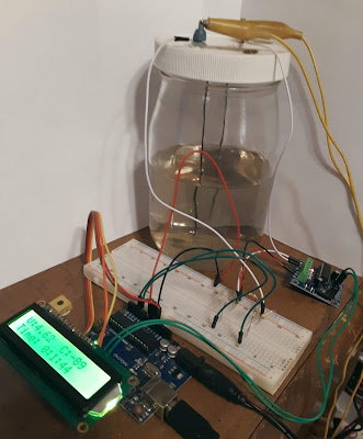
Here is a picture of the colloidal silver maker, but it was running off USB power and the CS container was only half full.  This time the L293 board is visible on the right side of the picture.

This picture shows the Colloidal Silver Generator actually running.  The Air pump stirrer has been added with 20 ohms in series to reduce the motor noise.  Also the motor ground must be separate from the other grounds because of all the electrical noise that the motor makes.
Arduino Colloidal Silver Maker
Here is another picture.  The resistor divider and L293 motor controller are now located on the top of the colloidal silver maker.  Eight wires then run down to the Arduino.  There are two ground wires, one ground wire for the motor controller and one ground wire for the voltage divider.

After the second test run with the current staying under .5 ma, and 1 ma being the ideal current, I am thinking that it needs to to be modified from 12 volts to 20 volt operation.  Most Colloidal silver makers use 24 to 28 volts. The L293 can operate up to 30 volts, but the Arduino voltage regulator has a maximum of 20 volts, and the air pump stirrer has a maximum of 12 volts. The air pump runs best at around 9 volts.  So either a redesign will be needed to have some voltage regulators added, or I can try to use a 20 volt power source like that of an old laptop ac adapter.

I tested this design for a few minutes with a 19 volt laptop AC adapter.  Only 17.7 volts made it to the colloidal silver maker.  The Arduino voltage regulator got very warm but survived.  I disconnected the air pump for this test because it is rated for 12 volts maximum and runs best at 7-9 volts.  I have since added a PWM output from the Arduino for the air pump of 1/2 of the power source or 10 volts for 20 volt operation.

The Arduino's PWM ability is used to regulate the current to the Colloidal Silver maker to just under 1 ma. The over current shutdown is set to 2.0 ma.

There is a video of it running at this link: https://youtu.be/3ap4-GnGx_8

Here is the code so far:

/*****************************
Arduino Colloidal Silver Maker
By Bob Davis
April 2020

Use a 16x2 LCD display shield or equivalent
Shows the voltage, current, and run time.

The circuit:
 * LCD RS - D9
 * LCD Enable - D8
 * LCD D4 - D4
 * LCD D5 - D5
 * LCD D6 - D6
 * LCD D7 - D7
 * LCD R/W and VSS pin to ground
 * LCD VCC and LED pin to 5V
 * 10K variable resistor:
 * ends to +5V and ground
 * wiper to LCD VO pin (pin 3)
 * Uses L293 motor controller on D10 adn D11 for PWM ability
 * Uses L293 on D3 for stirrer motor.

*********************/

// include the library code:
#include <LiquidCrystal.h>

// initialize the library with the numbers of the

interface pins
LiquidCrystal lcd(9, 8, 4, 5, 6, 7);

// Pins for Colloidal silver maker
int CS1=10;
int CS2=11;
// Pins for stirrer
int Stir=3;
int Shutdown=0;
// Variables for time
int hours;
int minutes;
int seconds;
long hour = 3600000; // 3600000 milliseconds in an hour
long minute = 60000; // 60000 milliseconds in a minute
long second = 1000; // 1000 milliseconds in a second
float AN1=0.0; // Analog inut 1
float AN2=0.0;
float temp1=0.0;
float temp2=0.0;
float CUR=0.0;  // Current in ma
int CurSet=255; // Current Setting

void setup() {
  // set up the LCD's number of columns and rows:
  lcd.begin(16, 2);
  pinMode (CS1, OUTPUT);
  pinMode (CS2, OUTPUT);
  pinMode (Stir, OUTPUT);
}

void loop() {
  // Reverse current every 30 minutes
  if (Shutdown==0){
    analogWrite(Stir, 128); // 1/2 supply voltage
    if (minutes<30){
      analogWrite(CS1, 0);
      analogWrite(CS2, CurSet);
    }
    else{
      analogWrite(CS2, 0);
      analogWrite(CS1, CurSet);
    }
  }
  else{
    analogWrite(CS1, 0);
    analogWrite(CS2, 0); 
    analogWrite(Stir, 0); 
    }
  temp1=analogRead(A1);
  AN1=((temp1*5.0)/1024.0)*4.0;
  temp2=analogRead(A2);
  AN2=((temp2*5.0)/1024.0)*4.0;
  CUR=abs(AN1-AN2);
  if (CUR > 1.0) {CurSet--;} // Reduce PWM
  lcd.clear();
  lcd.setCursor(0,0);
  lcd.print("V:");
  lcd.print(AN1);
  lcd.setCursor(8,0);
  lcd.print("V:");
  lcd.print(AN2);
  lcd.setCursor(10,1);
  lcd.print("C:");
  lcd.print(CUR);
  // print the number of seconds since reset:
  long timeNow = millis();
  hours = (timeNow) / hour;             
  minutes = ((timeNow) % hour) / minute ;
  seconds = (((timeNow) % hour) % minute) / second;
  lcd.setCursor(0, 1);
  lcd.print("T:");
  lcd.print(hours);
  lcd.print(":");
  lcd.print(minutes);
  lcd.print(":");
  lcd.print(seconds);

  if (hours>3){ // Time under 4 hours
    Shutdown=1;
    }
  if (CUR>2.0){ // Current under 1ma
    Shutdown=1;
    }

  delay(300);
}

Tuesday, February 25, 2020

I am Making a DIY Clone of the CNC 3018

I recently built a CNC 3018 Pro for someone and blogged about it.  Now I have decided to rebuild my home made CNC to be like the 3018.

This picture compares the two machines side by side.
To be honest it would be cheaper to buy the kit on eBay.  I figured I had most of the parts so it would be cheaper but that is not the case!  If you bought all of the parts it would cost you over $200 and you can get the kit on eBay for around $140-150.

This picture shows how I wired the 3018 CNC

CNC 3018 wiring
 Using larger sized limit switches with a piece of 2" by 1" angle aluminum.
 More limit switch pictures.  I had a limit switch that had a sideways lever for the Z axis.
 Close up of smaller limit switches.  I could only get one screw because of the Allen screw that tightens against the rod.  I should have put the switch on the other side so the rods can be removed.
The controller board needs lots of repairs and even a software fix. You need to add pull up resistors to the inputs of the Pololu A4988 Stepper controllers.  Don't forget to remove the jumpers on the other side of the board as well.  Then you will need to add filter caps to D9, D10 and D12. The board has D11 as the Z axis limit switch but GRBL will use D12 instead.  D11 is used for the spindle control relay or transistor.  In software the "Step" and "Direction" pins are all swapped and need to be swapped back.  There are several web sites that tell how to do that.