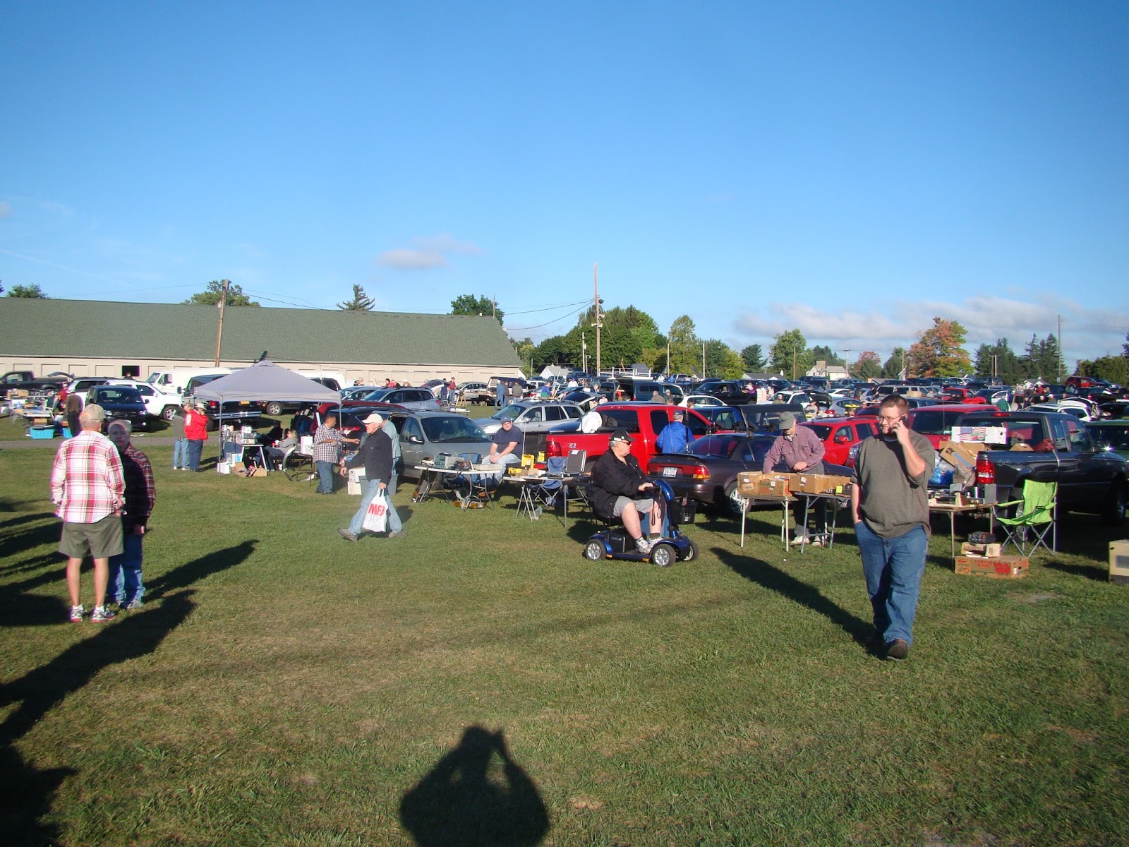
Sept 24 was the Hamfest (Radio Amature Flee Market) in Elmira/orseheads NY. This was my first time to go to this event. It was quite large and well attended. I did not buy much. My favorite purchase was 2 overflowing quarts of grapes. They were delisious! Other than that I bought a L/C/R meter for $15 and some VGA cables.
This was a really old projector, at least that is what the label said...
This is a picture of the event from the ground label.
This I think is a really old tube tester.
How about a 1000 watt RF amplifier?
This is my collection of stuff to sell. There is a lot of free stuff.
This is a picture of the event from a higher location.
I have been busy rebuilding my DIY CNC machine. It will be all metal when I get done. It will also include a USB interface, likely an Arduino. None of my computers have a parallel port these days. So something has to be done to resolve that issue.
This first picture is the new metal parts all drilled and ready for assembly. Well maybe ready to be filed so they can be assembled.....
Here is the first video, getting the electronics working again:
Here is the second video with the X and Y axis working:
I have finally ben able to get GRBL to work with my CNC.
You will need to install the Arduino software.
Then plug in the Arduino and install the driver.
Then Unzip and install the GRBL software into the Arduino library.
Then compile and upload the GRBL software into the Arduino.
Open the serial interface and set the baud rate at 115k
Then install Universal G-Code Sender on the a PC
Set the baud rate to 115K and you should now be able to control the CNC.
Now to get the limit switches to work.....
My latest upgrade is to mount the Arduino to the electrical area. The limit switches are still not wired up.
The Z axis is now working!
Here is the latest video:
By the way I tried one of the Arduino CNC shield's but the IC's got so hot that you could cook on them and then it started hanging up because it was overheating.
I recently added some more shelves in my lab to hold more books, videos and projects. Here is a couple of views of the room.
On the left side at the top there is my DVD video collection, below that there are my Volt/Ohm meters, cameras, etc. Lower down is my prototypes for my books in white plastic binders. Center is my project shelves with some dinosaurs and my CNC machine covered in stuff. At the bottom there is a cupboard that my dad built for me when I was a teenager.
In this picture is my free-to-me 32 inch TV mounted on the wall. Below that there is my free-to-me 17 inch laptop and a road kill 24 inch monitor (attached to the Raspberry Pi on the desk at this time). To the right of that is my Epson printer that was also given to me. The book shelf on the right side of the picture actually holds books as well as some parts bins and my CD / Software collection. The cute brown dog is something I made way back when I was in high school.
So there you have it, the room where all of my books have been written, the room where my inventions are being built.
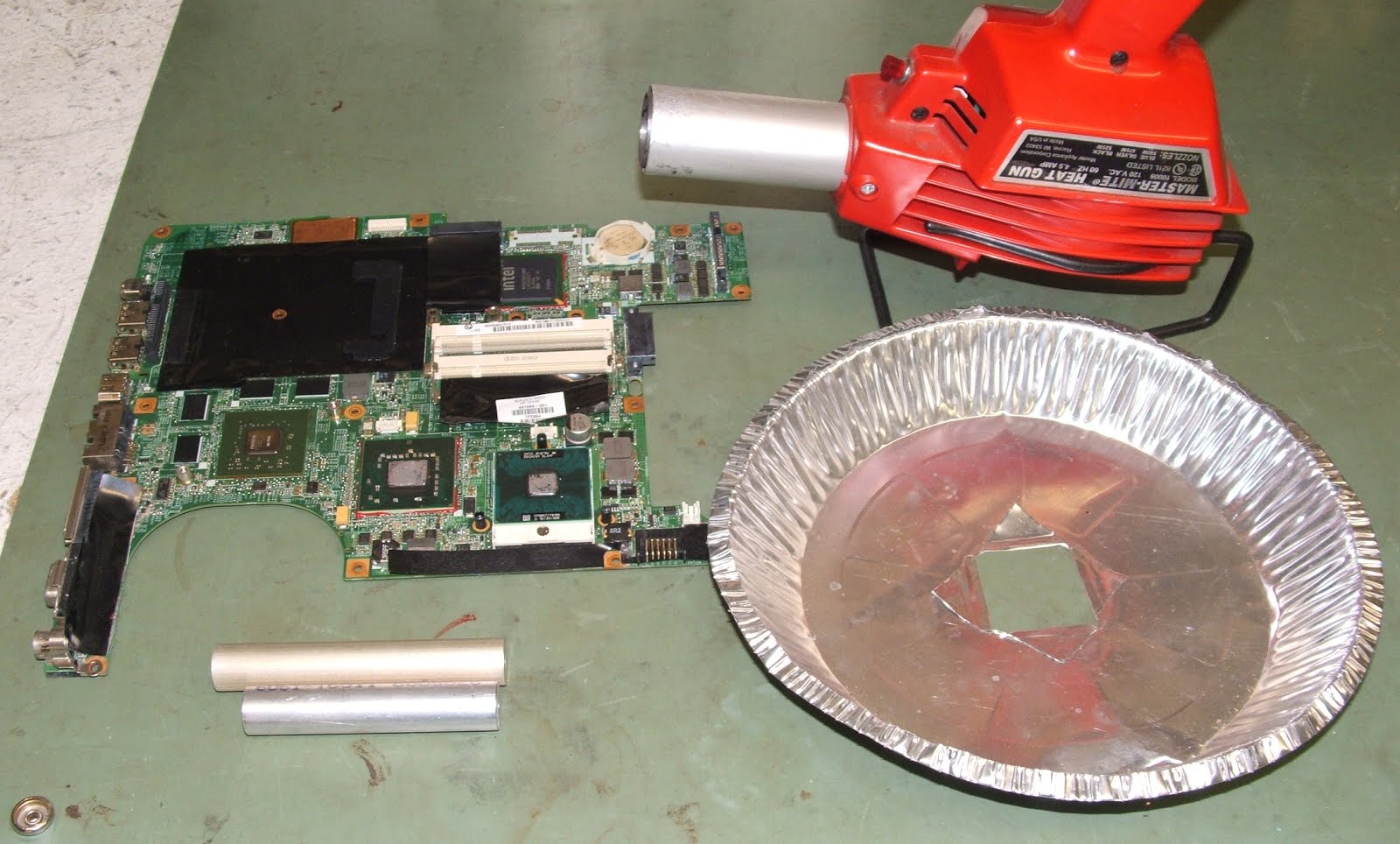
I know there are hundreds of other posts on this subject. I have now tried it and it works! The last time I sent the motherboard off and spent some money to fix it. I had two sick HP DV9700 laptop's and I could not even sell them for $40 on eBay. So with nothing to loose I thought I would give it a try myself.
You will need the following.
1. Spacers for under the motherboard to allow air flow underneath it.
2. An aluminum heat shield, a pie plate works
3. A heat gun capable of reaching about 450 degrees.
4. The defective motherboard.
5. A timer, a cell phone will do.
First run a time test. Set a piece of solder on a metal surface and with the heat gun one inch away from it see how long it takes to melt the solder. In my case it took 3 minutes. Set the motherboard on the spacers and center the heat shield over the GPU chip. In the picture above it is the left green chip located just above the center of the arc where the cooling fan goes. Start the timer and hold the heat gun in place moving it slightly to heat the top of the chip evenly. After the timer runs out let the motherboard cool slowly, like for 30 minutes before handling it or reassembling it.
Reassemble everything and hopefully you now have a working laptop! So far this has fixed every motherboard that I have tried it on. This fixes problems like CD ROM drive not recognized, No sound, garbage on screen, etc.
The 2016 Batavia Hamfest was the best Hamfest that I have attended this year. Maybe also one of the biggest in Batavia as well. I only spent a little over $20. For that I purchased two studio quality TV cameras (They were not the new widescreen format, but they work!) and a laptop computer. There was also a 25 foot VGA extension cord for 25 cents!
There was lots of interesting stuff for sale too. This was some sort of antenna tuner.
How is this for a really old tube tester?
Portable radios by the box full....
This is where I bought the two TV cameras.
Oh, and here is my stuff. Mostly free stuff....
Here is some more neat radios.
How about a genuine HH Scott radio?
This vacuum tube amplifier looks great. Reminds me of the first amp I built, but looks lots better.
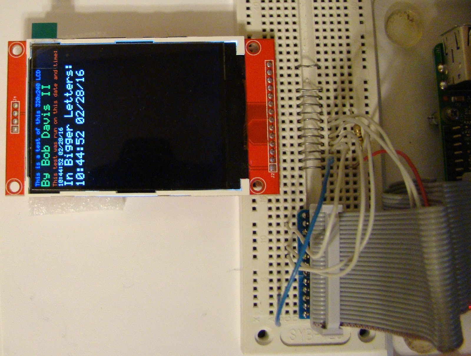
I have succeeded in writing the code for the SSD1289 screen to work with a Raspberry Pi. I also added a control panel so I have more variable resistors. I used them to vary the color giving 256K colors.
The SSD1289 took a flexible ribbon cable to connect it up. That is because you have to access both rows of pins.
I have removed the wall between the dining room and kitchen. This creates an open concept, making the living room and kitchen seem bigger.
Being a mobile home there was already two 8 inch by 2 inch laminated beams down the center. There was a one inch gap in the center between the beams that was filled with plywood to bring the beam size to 8 inches by 5 inches. The existing wall was not a supporting wall as it was only under one of the beams and was made out of two pieces, having a top and bottom half. The beam was then covered with 1 by 8's to make it look better.
To fix the floor was a little bit tricky as the flooring material was no longer available. I found some similar laminated flooring that almost matched the old flooring and then used that. I used a real oak bridge to fill the gap between the laminate of the living room and the kitchen flooring.
After about 2 weeks of trying I finally got a parallel interface LCD to work in Python. I converted the code from C for the Arduino. It did not appear to be working until I slowed it way down and discovered little lines appearing on one of the LCD's. The driver is roughly a ILI9325 driver based on the Arduino code and the ILI9325 specifications.
The picture shows two screens and they both work with the same software.
Here is what the text looks like on the other screen.
Here is the first video demonstrating that it works.
Here is a second video, I added a Analog to Digital converter and made an "Etch-a-Sketch".
The 2016 Chaffee Hamfest was last weekend. It was supposed to rain so we used the pavilions. It was a little too windy for my books so I kept them in a box, and hence did not sell many of them. I did sell about 1/2 of the stuff that I brought.
This first picture is of my stuff for sale.
Here is the next pavilion.
Here is a picture of the main pavilion.
This next picture is of the Pioneer school's stuff.
I used to go to a lot of Hamfests but these days I only get to two or three of them every year.
The Raspberry Pi Zero was supposed to be a $5 single board computer. However they were quickly bought up and resold for $25 or more. With the introduction of the Raspberry Pi Zero camera edition the prices are now coming down to around $18. So I bought one and a kit to be able to use it for another $15. To be able to use the Zero you will need a micro SD card with NOOBS on it, a 5V 2 Amp AC adapter, a mini USB to regular USB adapter/hub and a Mini HDMI to regular HDMI adapter/cable. A case to hold it in helps a lot too. To be able to use the GPIO pins you will need to solder in your own 26 or 40 pin header.
This first picture is of the Raspberry Pi Zero camera edition.
This picture shows the Raspberry Pi 1A, 2B, and Zero next to each other.
This third picture shows the Raspberry Pi's in their cases. I have a model 2/3 case on order from china that has not arrived yet.
As far as cases go the case on the left broke off one of the corners. The hole for the ribbon cable does not fit the ribbon cable connector. I was not happy with that style of case. The case for the zero consists of two layers of Plexiglas and that style of case is what I ordered for the Raspberry Pi 2.
Over the holiday weekend I finished up writing my code for this 2.8 inch LCD. It can now do bmp graphics as well as text and even large text. All of the code is written in Python, so there are no dependencies except for SPI support that is now built into the Raspberry Pi operating system.
This picture shows a sample of the text. It supports colors as two sizes of text.
I have written six books on the Arduino, but only one on the Raspberry Pi. Now I am working on a second Raspberry Pi book called, "Raspberry Pi LCD Projects". The third LCD init is this 1.8 inch 128x160 pixel color LCD. This first picture was taken when I first got it to work doing a Red/Green/Blue test.
Then I worked on the setup configuration so that instead of using 4 bits or 5 bits per color it uses 6 bits per color or three bytes per color. That way it matches up with the BMP file format making it very easy to display a BMP image. Sorry but my camera does not show the colors very well.....
I used IrfanView to edit and create this 128 by 160 Raspberry Pi logo image.
At first the BMP pictures appeared to be out of sync. The problem was that the code for this display that is listed on the Internet is wrong. The display was not using all of its 128 pixels in the width. After a few tweaks everything came up working as it should.