Monday, March 7, 2022

I am Making my Third Humanoid Robot

I have started on making my third humanoid robot.  This one is modeled after the EZ-Robot JD Humanoid.  The issue with the larger humanoids is that their center of gravity is way too high.  There is a two degree tolerance in each servo and that is amplified by the distance from the servo's.  So in a humanoid that is over 16" tall the two degrees can amount to falling over frontwards or falling over backwards.  That makes it really hard to write software for walking.  

One solution is to make the robot shorter and to make the distance from each servo shorter.  In the following picture there is a servo for the EZ_Robot on the left, for the Hadron Robot in the middle, and for the mechanical robot sold on eBay on hte right.  The EZ-Robot assembly is so short that the ears need to be cut off the one end of the servo for it to work.  The Hadron robot on the other hand is not much smaller than the mechanical version, it also is not quite square.


As I tried more options the possibilities expanded to five different versions.  I think I will have to design my own!


The robot body would take 16 hours to print as designed.  I turned it over and that reduced the time to 10 hours.  However since there would be supports under the front, the front surface is not a smooth.  
Then I ran into the issue with the shoulder servos needing their tabs cut off.  What is it with the designers and cutting the mounting tabs off the servos??


My solution was to cut some slots in the top for the servo mounting tabs.  I used a soldering iron to do that trick.  BTW when I added the legs the body broke in half!  These parts fit way too tight.  I file them off so they are smooth before even trying to fit them together.

The robot is now about 1/2 way completed.  Here is what he looks like so far.

The next issue was that the shoulders (Servo horn extenders) keep breaking in half.  So I rotated them so they stand up before printing them and that seems to fix the issue.


The U brackets for the legs kept breaking.  So I developed my own design.  

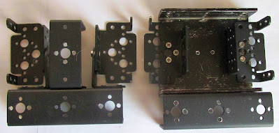
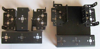
So far I have come up with six different servo U bracket design options.  The five on the left do not require you to cut off the servo mounting tabs and they do not break as easily as the ones normally used for this robot.  Somehow I lost the mounting holes in the fifth one but I added them back in later on.


So far he is coming together. The head has too big of an opening for the LCD screen.  I cut it for a 2.5" LCD but then the screen did not fit because the LCD circuit board was too big.  I may have to make a bezel for the LCD to cover the mistakes.....

I almost gave up on his hands.  I have piles of servos but none are the size that properly fit his hands.  There is a size of servo that is in between the SG90/HS55 and the normal sized servo (They are marked "PKZ1060") but even they do not fit.  So I modified the hands to use the SG90 sized servos.  I had to drill out the servo end so the white servo arm would fit through it then I melted a hole for the screw that locks the arm to the printed arm.


I had to remove the left side (It broke off anyway) and then trim a little for the round part of the servo to fit.  Then I used lots of glue to hold the servo in place.  I had trouble with mounting the hands to the arms so I added a screw, as can be seen below the servo in this picture.


Here is what he looks like with his hands attached.  Now to add a servo controller.


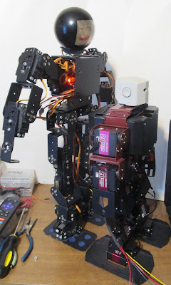
This next picture is a size comparison.  JD Humanoid is in the front left.  To the right is the Robosoul HS3 and behind them is the humanoid that is sold on eBay.


Simple Arduino TFT LCD Robot eyes

I am working on making some better "eyes" for my humanoid robots. The 8x8 LED design was cool but I can do a lot more with an LCD screen.  I need to make it more universal to work with different sizes of screens.


This is a link to the video of this robot head being printed:

Here is the code so far:
// Program for Eyes on a 1.8" TFT LCD Screen

#include <TFT.h>  // Arduino LCD library
#include <SPI.h>
 
// Pins
#define cs   10
#define dc   9
#define rst  8
 
// Create an instance of the library
TFT TFTscreen = TFT(cs, dc, rst);
 
void setup() {
 
   // Initialize the screen
   TFTscreen.begin();
 
   // Clear the screen
   TFTscreen.background(0, 0, 0);
 
   // Set font color to white
   TFTscreen.stroke(255,255,255);
 
   // Set the font size
   TFTscreen.setTextSize(2);
 
   // Write some text on the screen
//   TFTscreen.text("Hello World!",0,0);
}
 
void loop() {
   TFTscreen.noStroke();
   // Eyes Center
   TFTscreen.fill(255,255,255);
   TFTscreen.circle(20,60,20);
   TFTscreen.circle(50,60,20); // oblong circle
   TFTscreen.rect(20,40,30,41);
   TFTscreen.fill(255,0,0);
   TFTscreen.circle(35,60,20);
   TFTscreen.fill(0,0,0);
   TFTscreen.circle(35,60,10);

   TFTscreen.fill(255,255,255);
   TFTscreen.circle(110,60,20);
   TFTscreen.circle(140,60,20);// oblong circle
   TFTscreen.rect(110,40,30,41);
   TFTscreen.fill(255,0,0);
   TFTscreen.circle(125,60,20);
   TFTscreen.fill(0,0,0);
   TFTscreen.circle(125,60,10);
   delay(1000);

   // Eyes Narrow
   TFTscreen.fill(0,0,0);
   TFTscreen.rect(0,40,160,10);
   TFTscreen.rect(0,70,160,11);
   delay(1000);
   
   // Eyes Big
   TFTscreen.fill(255,255,255);
   TFTscreen.circle(30,60,30);
   TFTscreen.circle(40,60,30); // oblong circle
   TFTscreen.rect(20,40,30,41);
   TFTscreen.fill(255,0,0);
   TFTscreen.circle(35,60,20);
   TFTscreen.fill(0,0,0);
   TFTscreen.circle(35,60,10);

   TFTscreen.fill(255,255,255);
   TFTscreen.circle(120,60,30);
   TFTscreen.circle(130,60,30);// oblong circle
   TFTscreen.rect(110,40,30,41);
   TFTscreen.fill(255,0,0);
   TFTscreen.circle(125,60,20);
   TFTscreen.fill(0,0,0);
   TFTscreen.circle(125,60,10);
   delay(1000);
   TFTscreen.fill(0,0,0);
   TFTscreen.rect(0,30,160,61); // Erase eyes


   // Eyes Right
   TFTscreen.fill(255,255,255);
   TFTscreen.circle(20,60,20);
   TFTscreen.circle(50,60,20); // oblong circle
   TFTscreen.rect(20,40,30,41);
   TFTscreen.fill(255,0,0);
   TFTscreen.circle(20,60,20);
   TFTscreen.fill(0,0,0);
   TFTscreen.circle(20,60,10);

   TFTscreen.fill(255,255,255);
   TFTscreen.circle(110,60,20);
   TFTscreen.circle(140,60,20);// oblong circle
   TFTscreen.rect(110,40,30,41);
   TFTscreen.fill(255,0,0);
   TFTscreen.circle(110,60,20);
   TFTscreen.fill(0,0,0);
   TFTscreen.circle(110,60,10);
   delay(1000);
   
   // Eyes Left
   TFTscreen.fill(255,255,255);
   TFTscreen.circle(20,60,20);
   TFTscreen.circle(50,60,20); // oblong circle
   TFTscreen.rect(20,40,30,41);
   TFTscreen.fill(255,0,0);
   TFTscreen.circle(50,60,20);
   TFTscreen.fill(0,0,0);
   TFTscreen.circle(50,60,10);

   TFTscreen.fill(255,255,255);
   TFTscreen.circle(110,60,20);
   TFTscreen.circle(140,60,20);// oblong circle
   TFTscreen.rect(110,40,30,41);
   TFTscreen.fill(255,0,0);
   TFTscreen.circle(140,60,20);
   TFTscreen.fill(0,0,0);
   TFTscreen.circle(140,60,10);
   delay(1000);
 
}


Wednesday, February 23, 2022

Rebuild of the 17 DOF Humanoid Robot found on eBay

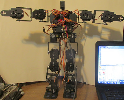
 In my book "Arduino Servo Projects" I made all kinds of Humanoid Robots.  But none of them were the 17 DOF Humanoid as is found on eBay.  I just could not get it to work.  It has a high tendency to fall over a lot.  In this guys video it fell off the table: https://www.youtube.com/watch?v=-gQDgxQkX-w !  So I spent some time trying to fix him.  One thing I noticed is that his legs are too long.  Even with the higher power MG958 servos when he falls over and I pick him up the servos then go to where they were supposed to.  The servos just cannot lift his weight!  Then as I was studying him I found the mistake!  Can you see it in the pictures below?


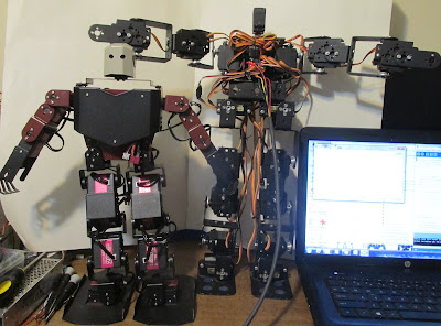
Here I am comparing him to the robot from RoboSoul - the HS3 (I made an imitation version and he works just like the real one)


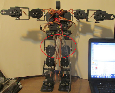
Did you find the problem?  I circled it in red in this picture.  The servo is mounted upside down!


While I was at it I also changed his chest.  The goal there was to make it more like the one that comes in the kit on eBay.  The only difference now is that his head is 3/4 of an inch taller.  I had to move the electronics to the front too.

This first picture is of the new chest bracket on the right.  It closely matches the kit on the left.  The chest is made out of a 3.5 inch piece of three inch by one inch C Channel aluminum.

This is the old chest bracket on the right.  The arms were located higher up and one inch forward of the kit design.  This gave lots of room for the electronics in the back.


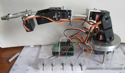
I rebuilt my Arduino Servo Arm to use Switches!

This change started as an accident.  Somehow I broke one of the variable resistors that controls the servos in the arm.  So after a while I came up with the idea of using switches instead. For the switches you need 3 position ones.  The positions are on low off and on high.  Then add two 10K resistors across the switch with the two resistors meeting in the middle.  The resulting operation of the arm was much smoother and quieter.  The variable resistors picked up too much noise and that resulted in herky-jerky motion.

This first picture is of the back of the switches.  I used 33K resistors as the value is not critical.


This is the front view of the robot arm controlled by switches.

This is a video of it in operation:

Monday, February 14, 2022

15 DOF Humanoid with PCA9685 and MAX7219

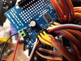
There was not enough pins available on my Arduino UNO to interface a LCD.  I was using 15 pins to control the servos.  So I added a PCA9685 servo controller.  It only uses 2 pins to control 16 servos, thus freeing up many pins for further experiments.  

When I first fired up the PCA9685 shield it quickly smoked.  The polarity protection transistor could not handle the current.  So I replaced it with a jumper wire for now.  The transistor is located next to the power connector near where it says "GND".


Here is the video of the robot:

https://www.youtube.com/watch?v=u30YtSnnPJE

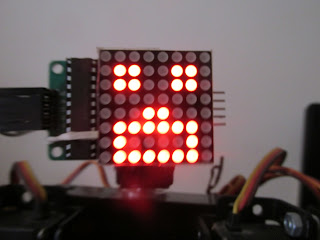
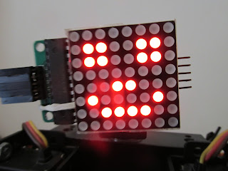
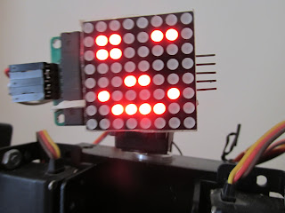
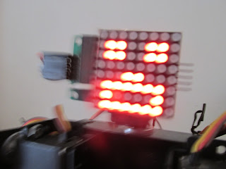
Here are some of the robots facial expressions:


In this picture you can almost see the fear in his eyes!


Friday, February 4, 2022

Changing the head on my 15 DOF Humanoid robot

 I am working on different options for the head or face of my 15 DOF robot.  Today I got a MAX7219 8x8 LED array working with it.  Over the years I have made heads out of Christmas ornaments and some LED's.  But they cannot change their expression.  Now I have added a MAX7219 so the robots expression can change with every command that you send him.  

This picture shows some of the robot heads I have made for my robots with the MAX7219 version in the middle.  As you can see the 8x8 LED array is a little on the small side.  I have some bigger LED arrays that are two and three color, but without the MAX7219 I do not have enough pins left over on the Arduino processor to run them.  Data TX and RX + 15 servos is 17 Pins leaving only three pins that are available to control the face.

Max7219 Humanoid Robot Head

The video is up on YouTube:

https://youtu.be/3wDNV5jnZRc

Thursday, January 20, 2022

Hiwonder RoboSoul HS5 Humanoid Robot Demo


I have finally been able to run this robot.  I started the project about a year ago.  There was one bad servo that needed replacement.  Then I did not have the arm servos mounted correctly.  But he is up and running now.  You have to assign each servo a number with another interface board and different software before you can assemble the robot.

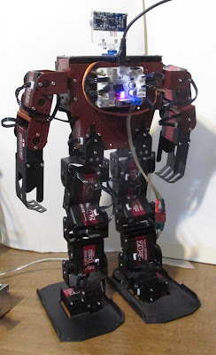
This is the back view of the robot.  The bus servo controller is not the correct one but it works anyway.


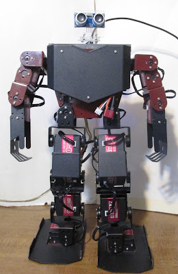
This is the front view of the robot.  I changed his head as the one that came with him was too angry looking.

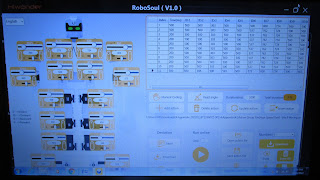
This is the control screen.  The software was downloaded from hiwonder.

This is a link to the video of the robot working on YouTube:

https://youtu.be/gvBmzbqPedI

Friday, January 7, 2022

72 x 16 WS2812B Addressable LED sign with Arduino Nano

I rewired another of my signs to have all of the LED's wired in series.  They will work with an ESP8266 or newer processor wired that way.  However I have, after a couple of days playing with the programming, done it with an Arduino Nano.  FastLed and AdaFruit NeoMatrix all create a large array then output it. This uses a lot of memory and hence limits the use of older processors. 

My software creates the output directly, eliminating the array stage.  The biggest issue is keeping the software fast.  For instance the Arduino Output "digitalWrite" command cannot be used, it is too slow.  I have to use direct port manipulation.  In the past I have outputted 8 bits to 8 LED strips using that technique.  Hower, by adding some shifting commands to the software I have done the same thing but I am only using D8 to actually talk to the LED sign.

This is what the LED sign looks like from the back side.

Here are some pictures of the text once I got the sign working.


The youTube video is at: https://youtu.be/rKZ0HcD0yVk

Here is the code:

// For Color Text on 1wire, Series wired WS2812 strings
// Features: Bluetooth support, 2 Lines, 5x7 Font
// by: BOB Davis January 2022

// Uses Port B for faster output of data
// Displays 2 lines of text switching between them.
// PORTB is Digital Pins 8-13 (Uses D8 actually)
// Colors: R=Red, G=Green, B=Blue, W=White
// Colors: Y=Yellow, P=Purple, C=Cyan

#define PIN 8 // D0 of port B - Actual pin to send data on

// Variables for colors of letters and background

int red=1; int green=1; int blue=1;

// Format: R/G/B=Foreground then R/G/B=Background then 1/2=line then text
String text1="G1ABCDEFGHIJKLMNOPQRSTUVWXYZ ";
String text2="R21234567890!@#$%^&*()_+{}[] ";
String textn=" "; // New text

// Send the next row to the pin 8 times.
// The delay timing is for an Arduino UNO or Nano.

void sendBits( byte bits ) {
// setting the MSB to 0 reduces brightness + power consumption
PORTB=0x0F; // turn on
PORTB=0x0F; // delay
PORTB=0x0F; // delay (add more for faster processors)
PORTB=0x00; // send data
PORTB=0x00; // delay
PORTB=0x00; // Turn off

for (int b=0; b<7; b++) {
PORTB=0x0F; // turn on
PORTB=0x0F; // delay
PORTB=0x0F; // delay (add more for faster processors)
PORTB=bits; // send data
PORTB=bits; // delay
PORTB=0x00; // Turn off
}
}

// Send bytes to LED's, avoid loops for maximum speed!
void sendPixelCol(byte Col) {
if (green)sendBits(Col); else sendBits(0x00);
if (red)sendBits(Col); else sendBits(0x00);
if (blue)sendBits(Col); else sendBits(0x00);
}

byte font5x7[][6] = { // font from AdaFruit
0x00, 0x00, 0x00, 0x00, 0x00, 0x00, // Space
0x00, 0x00, 0x5F, 0x00, 0x00, 0x00, // !
0x00, 0x07, 0x00, 0x07, 0x00, 0x00, //"
0x14, 0x7F, 0x14, 0x7F, 0x14, 0x00, //#
0x24, 0x2A, 0x7F, 0x2A, 0x12, 0x00,
0x23, 0x13, 0x08, 0x64, 0x62, 0x00,
0x36, 0x49, 0x56, 0x20, 0x50, 0x00,
0x00, 0x08, 0x07, 0x03, 0x00, 0x00, //'
0x00, 0x1C, 0x22, 0x41, 0x00, 0x00, //(
0x00, 0x41, 0x22, 0x1C, 0x00, 0x00, //)
0x2A, 0x1C, 0x7F, 0x1C, 0x2A, 0x00,
0x08, 0x08, 0x3E, 0x08, 0x08, 0x00,
0x00, 0x80, 0x70, 0x30, 0x00, 0x00,
0x08, 0x08, 0x08, 0x08, 0x08, 0x00,
0x00, 0x00, 0x60, 0x60, 0x00, 0x00,
0x20, 0x10, 0x08, 0x04, 0x02, 0x00, // /
0x3E, 0x51, 0x49, 0x45, 0x3E, 0x00, // 0
0x00, 0x42, 0x7F, 0x40, 0x00, 0x00, // 1
0x72, 0x49, 0x49, 0x49, 0x46, 0x00,
0x21, 0x41, 0x49, 0x4D, 0x33, 0x00,
0x18, 0x14, 0x12, 0x7F, 0x10, 0x00,
0x27, 0x45, 0x45, 0x45, 0x39, 0x00,
0x3C, 0x4A, 0x49, 0x49, 0x31, 0x00,
0x41, 0x21, 0x11, 0x09, 0x07, 0x00,
0x36, 0x49, 0x49, 0x49, 0x36, 0x00,
0x46, 0x49, 0x49, 0x29, 0x1E, 0x00, // 9
0x00, 0x00, 0x14, 0x00, 0x00, 0x00, // :
0x00, 0x40, 0x34, 0x00, 0x00, 0x00, // ;
0x00, 0x08, 0x14, 0x22, 0x41, 0x00,
0x14, 0x14, 0x14, 0x14, 0x14, 0x00,
0x00, 0x41, 0x22, 0x14, 0x08, 0x00,
0x02, 0x01, 0x59, 0x09, 0x06, 0x00,
0x3E, 0x41, 0x5D, 0x59, 0x4E, 0x00,
0x7C, 0x12, 0x11, 0x12, 0x7C, 0x00, //A
0x7F, 0x49, 0x49, 0x49, 0x36, 0x00,
0x3E, 0x41, 0x41, 0x41, 0x22, 0x00,
0x7F, 0x41, 0x41, 0x41, 0x3E, 0x00,
0x7F, 0x49, 0x49, 0x49, 0x41, 0x00,
0x7F, 0x09, 0x09, 0x09, 0x01, 0x00,
0x3E, 0x41, 0x41, 0x51, 0x73, 0x00,
0x7F, 0x08, 0x08, 0x08, 0x7F, 0x00,
0x00, 0x41, 0x7F, 0x41, 0x00, 0x00,
0x20, 0x40, 0x41, 0x3F, 0x01, 0x00,
0x7F, 0x08, 0x14, 0x22, 0x41, 0x00,
0x7F, 0x40, 0x40, 0x40, 0x40, 0x00,
0x7F, 0x02, 0x1C, 0x02, 0x7F, 0x00, //M
0x7F, 0x04, 0x08, 0x10, 0x7F, 0x00,
0x3E, 0x41, 0x41, 0x41, 0x3E, 0x00,
0x7F, 0x09, 0x09, 0x09, 0x06, 0x00,
0x3E, 0x41, 0x51, 0x21, 0x5E, 0x00,
0x7F, 0x09, 0x19, 0x29, 0x46, 0x00,
0x26, 0x49, 0x49, 0x49, 0x32, 0x00,
0x03, 0x01, 0x7F, 0x01, 0x03, 0x00,
0x3F, 0x40, 0x40, 0x40, 0x3F, 0x00,
0x1F, 0x20, 0x40, 0x20, 0x1F, 0x00,
0x3F, 0x40, 0x38, 0x40, 0x3F, 0x00,
0x63, 0x14, 0x08, 0x14, 0x63, 0x00,
0x03, 0x04, 0x78, 0x04, 0x03, 0x00,
0x61, 0x59, 0x49, 0x4D, 0x43, 0x00, //Z
0x00, 0x7F, 0x41, 0x41, 0x41, 0x00,
0x02, 0x04, 0x08, 0x10, 0x20, 0x00,
0x00, 0x41, 0x41, 0x41, 0x7F, 0x00,
0x04, 0x02, 0x01, 0x02, 0x04, 0x00,
0x40, 0x40, 0x40, 0x40, 0x40, 0x00,
0x00, 0x03, 0x07, 0x08, 0x00, 0x00,
0x20, 0x54, 0x54, 0x78, 0x40, 0x00, //a
0x7F, 0x28, 0x44, 0x44, 0x38, 0x00,
0x38, 0x44, 0x44, 0x44, 0x28, 0x00,
0x38, 0x44, 0x44, 0x28, 0x7F, 0x00,
0x38, 0x54, 0x54, 0x54, 0x18, 0x00,
0x00, 0x08, 0x7E, 0x09, 0x02, 0x00,
0x18, 0xA4, 0xA4, 0x9C, 0x78, 0x00,
0x7F, 0x08, 0x04, 0x04, 0x78, 0x00,
0x00, 0x44, 0x7D, 0x40, 0x00, 0x00,
0x20, 0x40, 0x40, 0x3D, 0x00, 0x00,
0x7F, 0x10, 0x28, 0x44, 0x00, 0x00,
0x00, 0x41, 0x7F, 0x40, 0x00, 0x00,
0x7C, 0x04, 0x78, 0x04, 0x78, 0x00, //m
0x7C, 0x08, 0x04, 0x04, 0x78, 0x00,
0x38, 0x44, 0x44, 0x44, 0x38, 0x00,
0xFC, 0x18, 0x24, 0x24, 0x18, 0x00,
0x18, 0x24, 0x24, 0x18, 0xFC, 0x00,
0x7C, 0x08, 0x04, 0x04, 0x08, 0x00,
0x48, 0x54, 0x54, 0x54, 0x24, 0x00,
0x04, 0x04, 0x3F, 0x44, 0x24, 0x00,
0x3C, 0x40, 0x40, 0x20, 0x7C, 0x00,
0x1C, 0x20, 0x40, 0x20, 0x1C, 0x00,
0x3C, 0x40, 0x30, 0x40, 0x3C, 0x00,
0x44, 0x28, 0x10, 0x28, 0x44, 0x00,
0x4C, 0x90, 0x90, 0x90, 0x7C, 0x00,
0x44, 0x64, 0x54, 0x4C, 0x44, 0x00, //z
0x00, 0x08, 0x36, 0x41, 0x00, 0x00,
0x00, 0x00, 0x77, 0x00, 0x00, 0x00,
0x00, 0x41, 0x36, 0x08, 0x00, 0x00,
0x02, 0x01, 0x02, 0x04, 0x02, 0x00,
0x3C, 0x26, 0x23, 0x26, 0x3C, 0x00,
0x1E, 0xA1, 0xA1, 0x61, 0x12, 0x00,
0x3A, 0x40, 0x40, 0x20, 0x7A, 0x00,
0x38, 0x54, 0x54, 0x55, 0x59, 0x00,
0x21, 0x55, 0x55, 0x79, 0x41, 0x00,
};

void sendline(String line) {
cli(); // No time for interruptions!
for (int c=0; c<8; c++){ // shift and send columns
for (int l=2; l<14; l++){ // Send characters
sendPixelCol((font5x7[(line)[l]-32][0])>>c);
sendPixelCol((font5x7[(line)[l]-32][1])>>c);
sendPixelCol((font5x7[(line)[l]-32][2])>>c);
sendPixelCol((font5x7[(line)[l]-32][3])>>c);
sendPixelCol((font5x7[(line)[l]-32][4])>>c);
sendPixelCol((font5x7[(line)[l]-32][5])>>c);
}
}
for (int c=0; c<8; c++){ // shift and send columns
for (int l=14; l<26; l++){ // Send characters
sendPixelCol((font5x7[(line)[l]-32][0])>>c);
sendPixelCol((font5x7[(line)[l]-32][1])>>c);
sendPixelCol((font5x7[(line)[l]-32][2])>>c);
sendPixelCol((font5x7[(line)[l]-32][3])>>c);
sendPixelCol((font5x7[(line)[l]-32][4])>>c);
sendPixelCol((font5x7[(line)[l]-32][5])>>c);
}
}
sei();
}

void setup() {
Serial.begin(9600); // opens serial port, data rate 9600 bps
pinMode(PIN, OUTPUT); // alternative set pin to output
}

void loop() {
if (Serial.available() > 0) {
textn=Serial.readString();
if ((textn[1])=='1') text1=textn;
if ((textn[1])=='2') text2=textn;
}
Serial.println(text1);
Serial.println(text2);

// Pad length to 40 characters
for(int i = text1.length(); i < 30; i++){ text1 += ' '; }
for(int i = text2.length(); i < 30; i++){ text2 += ' '; }

// Read colors from string,
if ((text1[0])=='R') red=1, green=0, blue=0;
if ((text1[0])=='G') red=0, green=1, blue=0;
if ((text1[0])=='B') red=0, green=0, blue=1;
if ((text1[0])=='W') red=1, green=1, blue=1;
if ((text1[0])=='Y') red=1, green=1, blue=0;
if ((text1[0])=='P') red=1, green=0, blue=1;
if ((text1[0])=='C') red=0, green=1, blue=1;

sendline(text1);
delay(4000); // Wait to display results

// Get New foreground and background colors
if ((text2[0])=='R') red=1, green=0, blue=0;
if ((text2[0])=='G') red=0, green=1, blue=0;
if ((text2[0])=='B') red=0, green=0, blue=1;
if ((text2[0])=='W') red=1, green=1, blue=1;
if ((text2[0])=='Y') red=1, green=1, blue=0;
if ((text2[0])=='P') red=1, green=0, blue=1;
if ((text2[0])=='C') red=0, green=1, blue=1;

sendline(text2);
delay(4000); // Wait to display results
return;
}

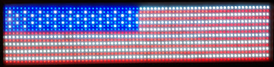
I have done some basic graphics, in this case a flag.  Basically its one byte per pixel.  Its easy to do as there is no math needed.  The big issue is the need for two 5 volt 15 amp power supplies to power it up.


Tuesday, January 4, 2022

DR-14830 LED Sign Modification to Arduino Interface

This summer I had purchased a LED sign.  On a closer observation I discovered that I cannot read the model number.  The sign contains two LED circuitboards with "DR-14830" on them.  Since I have been modifing LED signs to work with the Arduino for over 12 years now, this sign was another challenge for me to figure out.  It uses 74LS164 shift registers with ULN2003 drivers for the columns.  The rows are selected by a 74LS164 then a 74LS138 then a ULN2003 then TIP122 power transistors.  The power transistors go to the anodes of the LED arrays.  The row selecting 74LS164 was in the chain of shift registers so I removed it to make the software simpler to write.  

This is a picture of the back panel, as you can see the model number is not readable.

This is a wider view of the back.  It used to have two power sources of 9 VAC that were rectified and regulated to 9VDC for the TIP122 power transistors and 5 VDC for the logic IC's.  I changed it to run off a 5VDC at 10 amps switching power supply instead.


The 74LS138 pins 1, 2, 3 need to be jumpered to the unused 4 pins of the interconnecting jack. Pins 4 and 5 need to be connected to ground and pin 6 goes to 5 volts via another jumper wire.  Also you can see how I changed the power input to be only 5 VDC in this picture.


Before using the 4 unused pins cut the two wire runs that are running to them.  Pin 1 (and 5) is ground so skip that pin and use pins 2, 3, 4 to be connected to pins 1, 2, 3 of the 74LS138.  Existing Pin 7 is data and Pin 8 is clock.


I removed U7 and U8 as they were a phase locked loop (NE556) and a 74LS164 shift register for the 74138 address pins.  Then I cut a run (that was going to the 74LS138) and added the jumper wire in the picture to connect the buffered data to the first 74164 shift register instead of the now removed 74LS164 row selecting shift register.

After a couple hours of troubleshooting the sign started working.  I will eventually upload the software once I get it fine tuned.


Here is the code:

// 60x7 LED Sign driver
// Uses Some direct port writes
// 1/4/2022 by Bob Davis

//#define A   A0  74138 pin1
//#define B   A1  74138 pin2
//#define C   A2  74138 pin3
#define DAT 7 // 74LS164 Data 
#define CLK 8 // 74LS164 Clock 
#define ROW_PORT   PORTC  // Port the 74138 rows are connected to

String text1="ARDUINO UNO ";

// This font from http://sunge.awardspace.com/glcd-sd/node4.html
byte font[][7] = {
0x00,0x00,0x00,0x00,0x00,0x00,0x00, // ascii 32
0x00,0x00,0xfa,0x00,0x00,0x00,0x00, // !
0x00,0xe0,0x00,0xe0,0x00,0x00,0x00, // "
0x28,0xfe,0x28,0xfe,0x28,0x00,0x00, // #
0x00,0x34,0xfe,0x58,0x00,0x00,0x00, // $
0xc4,0xc8,0x10,0x26,0x46,0x00,0x00, // %
0x6c,0x92,0xaa,0x44,0x0a,0x00,0x00, // &
0x00,0xa0,0xc0,0x00,0x00,0x00,0x00, // '
0x00,0x38,0x44,0x82,0x00,0x00,0x00, // (
0x00,0x82,0x44,0x38,0x00,0x00,0x00, // )
0x10,0x54,0x38,0x54,0x10,0x00,0x00, // *
0x10,0x10,0x7c,0x10,0x10,0x00,0x00, // +
0x00,0x0a,0x0c,0x00,0x00,0x00,0x00, // ,
0x10,0x10,0x10,0x10,0x10,0x00,0x00, // -
0x00,0x06,0x06,0x00,0x00,0x00,0x00, // .
0x04,0x08,0x10,0x20,0x40,0x00,0x00, // /
0x7c,0x8a,0x92,0xa2,0x7c,0x00,0x00, // 0
0x00,0x42,0xfe,0x02,0x00,0x00,0x00, // 1
0x42,0x86,0x8a,0x92,0x62,0x00,0x00, // 2
0x84,0x82,0xa2,0xd2,0x8c,0x00,0x00, // 3
0x18,0x28,0x48,0xfe,0x08,0x00,0x00, // 4
0xe4,0xa2,0xa2,0xa2,0x9c,0x00,0x00, // 5
0x3c,0x52,0x92,0x92,0x0c,0x00,0x00, // 6
0x80,0x8e,0x90,0xa0,0xc0,0x00,0x00, // 7
0x6c,0x92,0x92,0x92,0x6c,0x00,0x00, // 8
0x60,0x92,0x92,0x94,0x78,0x00,0x00, // 9
0x00,0x6c,0x6c,0x00,0x00,0x00,0x00, // :
0x00,0x6a,0x6c,0x00,0x00,0x00,0x00, // ;
0x00,0x10,0x28,0x44,0x82,0x00,0x00, // <
0x28,0x28,0x28,0x28,0x28,0x00,0x00, // =
0x82,0x44,0x28,0x10,0x00,0x00,0x00, // >
0x40,0x80,0x8a,0x90,0x60,0x00,0x00, // ?
0x4c,0x92,0x9e,0x82,0x7c,0x00,0x00, // @
0x7e,0x90,0x90,0x90,0x7e,0x00,0x00, // A
0xfe,0x92,0x92,0x92,0x6c,0x00,0x00, // B
0x7c,0x82,0x82,0x82,0x44,0x00,0x00, // C
0xfe,0x82,0x82,0x82,0x7c,0x00,0x00, // D
0xfe,0x92,0x92,0x92,0x82,0x00,0x00, // E
0xfe,0x90,0x90,0x80,0x80,0x00,0x00, // F
0x7c,0x82,0x82,0x8a,0x4c,0x00,0x00, // G
0xfe,0x10,0x10,0x10,0xfe,0x00,0x00, // H
0x00,0x82,0xfe,0x82,0x00,0x00,0x00, // I
0x04,0x02,0x82,0xfc,0x80,0x00,0x00, // J
0xfe,0x10,0x28,0x44,0x82,0x00,0x00, // K
0xfe,0x02,0x02,0x02,0x02,0x00,0x00, // L
0xfe,0x40,0x20,0x40,0xfe,0x00,0x00, // M
0xfe,0x20,0x10,0x08,0xfe,0x00,0x00, // N
0x7c,0x82,0x82,0x82,0x7c,0x00,0x00, // O
0xfe,0x90,0x90,0x90,0x60,0x00,0x00, // P
0x7c,0x82,0x8a,0x84,0x7a,0x00,0x00, // Q
0xfe,0x90,0x98,0x94,0x62,0x00,0x00, // R
0x62,0x92,0x92,0x92,0x8c,0x00,0x00, // S
0x80,0x80,0xfe,0x80,0x80,0x00,0x00, // T
0xfc,0x02,0x02,0x02,0xfc,0x00,0x00, // U
0xf8,0x04,0x02,0x04,0xf8,0x00,0x00, // V
0xfe,0x04,0x18,0x04,0xfe,0x00,0x00, // W
0xc6,0x28,0x10,0x28,0xc6,0x00,0x00, // X
0xc0,0x20,0x1e,0x20,0xc0,0x00,0x00, // Y
0x86,0x8a,0x92,0xa2,0xc2,0x00,0x00,  // Z
};

void setup() {
  pinMode (DAT,OUTPUT);
  pinMode (CLK,OUTPUT);
  pinMode (A0,OUTPUT);
  pinMode (A1,OUTPUT);
  pinMode (A2,OUTPUT);
  Serial.begin(9600);    // opens serial port, data rate 9600 bps
}
     
void loop() {
    if (Serial.available() > 0) {
      text1=Serial.readString();
      }
    Serial.print(text1);
    for (int r=0; r<7; r++){         // Select the Row
      for (int ch=10; ch>-1; ch--){  // select the character
        for (int c=5; c>-1; c--){    // select the column within character
          PORTC=7;                   // Turn display off while shifting
          digitalWrite(DAT, LOW);    // Check of data high or low
            if ((font[text1[ch]-32][c] >> r+1) & 0x01==1) digitalWrite(DAT, HIGH);
          digitalWrite(CLK, HIGH); 
          digitalWrite(CLK, LOW);  // Toggle clock
        }
      }
      PORTC=(r);       // row is done so display it
      delay(1);        // increase to troubleshoot    
    }
  }

This is a picture of the complete sign running.  I am sorry it is out of focus as the LED's are so bright that it overloads the camera.


To daisy chain the sign modules together you will need to extend the 74LS138 address pins to the next assembly.  I added a 4 pin connector to do that but the pins are wired backwards in the picture.  I made a custom cable to reverse the order of pins back to their correct order.


Monday, December 27, 2021

RGB or RGBW LED Strip Quick Controller

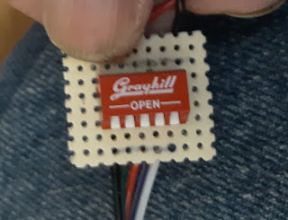
I recently had a situation where someone had purchased some RGBW LED strips, but he had no controller and needed the light strips to work within a few hours.  So I took a small piece of circuit board and a 5 position DIP switch and made a quick controller.

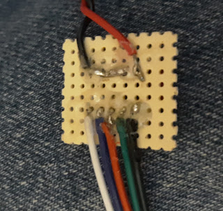
On the bottom side the five pin connector for the LED strip just goes to the five pins of the switch.  On the opposite side of the switches the black wire for the strip goes to +12 volts via a switch, the other wires go to ground via the switches.  This can be seen in the next picture.  A 12 volt AC adapter powers the LED strip.

From the top view the switches line up with the colors of the other wires.  That is to say the white wire is "White" LED's. The red wire is Red color, the green wire is Green color, and the blue wire lines up with theBlue color.

UPDATE: I eventually made several mini switch boxes for the LED switches.  


This is what one looks like when installed.


Thursday, December 9, 2021

Chevy Aveo Headlight Wiring Burning Up Issue

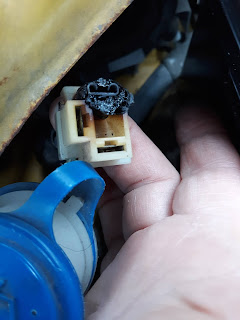
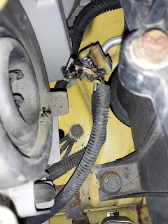
 My daughter said that one of her headlight was rather dim.  When I opened the hood I immediatly smelled the burnt electrical smell.  I looked at the dim headlight and the ground connector was burned off.  I attempted to cobble the bad headlight connector.  Then when I tested it the other headlight went out.  It had the exact same issue.  

Burnt Aveo Headlight Connector

Burnt Aveo Headlight Connector

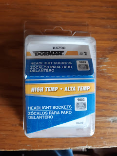
The fix is at auto zone,  For 13.99 you get two headlight socket replacement connectors with short wires attached.  The repair kit is Dorman 84790 and it includes two sockets.
Headlight Socket Repair Kit

This is the left passenger side headlight repaired.  You will need to also purchase 6 red crimp connectors.

This is the right, drivers side headlight.  The fill tube for the wipers can be removed to give more room to work.
Repaired Aveo Headlight connector